Design

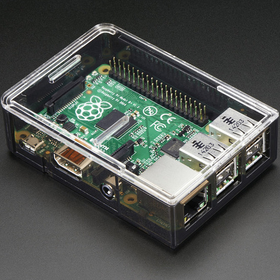
RaspberryPi Bare Metal
One of the big challenges of this project was programming the Raspberry Pi in bare metal, that is, without any operating system. This involved writing some simple startup code and a small library to interface with the processor's peripherals (such as the NEON VFP, timers, interrupts, UART controller, and GPIO). This was a rather involved process, so it will be broken down step by step. Most of this information was gathered from the Valvers tutorials on bare metal programming and David Welch's GitHub. The two approach this problem in different ways and we mixed the two approaches to develop a solution that worked for this project. Additionally, we regularly referenced the ARMv7 Technical Reference Manual (requires a quick and free NDA from ARM by registering on their website, so a link cannot be provided) and the BCM2835 Peripheral Manual, which describes the features of the processor outside of the ARM Core.
Startup and Initialization
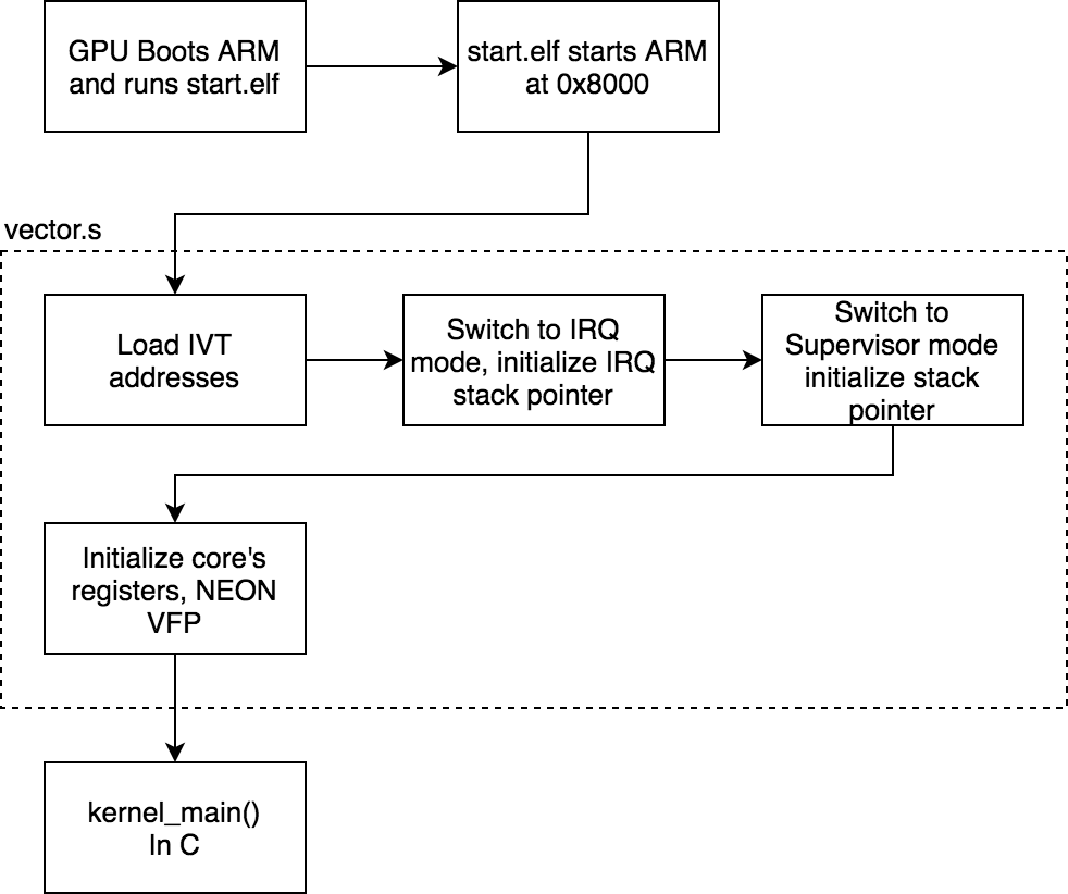
The Raspberry Pi boots by starting the GPU, which loads the start.elf into the ARM processor, triggers a reset on the ARM processor, and begins running the kernel.img. The kernel.img is the actual program.
The RPi's ARM processor requires the start of the program to be at address memory 0x8000. As with any C program, the gcc linker looks for the _start section and makes that the start of the program. The linker and memory map file handle placing the _start section at the proper memory address. The program begins in the vector.s assembly program. Here you will find the _start label. This code does the following:
- Set up interrupt vectors.
- Initialize the stack pointers for IRQ mode and Supervisor mode.
- Initialize the NEON VFP (hardware floating point unit)
- Call the C main function kernel_main
The very first thing the program does is set up the Interrupt Vector Table (IVT). Whenever the processor generates an exception (an interrupt), it will look up where the interrupt handler is stored in the IVT. After a reset, the reset exception is generated, so a reset handler is defined which contains all of the startup code. The handler calls an initialization function(_init_core), then calls the C function kernel_main, which is the actual code for the program. The rest of the assembly program defines convenience functions for interacting with registers, enabling/disabling the IRQ handler, and the IRQ handler itself.
Once the main kernel function is called by the startup code, it runs a higher level initialization function to turn on other peripherals, such as the UART and ARM Timer. At this point, code is application specific and not necessarily required for the processor to run.
Multicore
The Raspberry Pi 3 has 4 cores that can run in parallel. After a reset, core 0 runs the code while cores 1-3 wait for a signal from core 0 to start running. This signal comes in the form of writing the address of the function the core should run to a specific address that each secondary core will be checking.
One of the issues discovered is that GPIO does not play well with multicore. So only core 0 can interface with GPIO and the other cores can only perform computation. This issue was not explored further in the interest of time and project completion.
C Standard Library
One useful feature is the ability to link the C Standard Library. This features math functions, string manipulation functions, and string formatting (printf()). This requires that standard Linux system calls be implemented (accomplished in syscalls.c). Most of the functions can be trivially implemented to return 0. The one interesting function is the _write() function, which is used by printf() to display the characters in the formatted string. The function is implemented by writing the desired string to the UART interface (which must be initialized before any printing calls are made). This allows the printf() function to be used for serial debugging.
Motion Control
The CNC controller is designed to interface with step/direction stepper motors and AS5161 absolute magnetic encoders to create closed loop feedback control of the stage's position. This breaks down into three parts: sending step/direction pulses, reading encoders, and performing PID calculations. This process is performed for each axis independently.
Stepper Motor Control
A typical stepper motor is controlled with two signals: step and direction. The value of "direction" sets the direction of rotation--clockwise or counterclockwise. On each rising edge of the "step" signal, the motor will "step" to its next position. Typically, each step is 1.8°. When step signals are sent in quick succession, the rotation of the motor will appear smooth.
The step signal is generated using the ARM timer and interrupts. The timer is set to trigger an interrupt every 16 microseconds. This established the step clock that the step signal will be synchronized to. A global variable sets the number of these step clock pulses between each step pulse. The speed of rotation is proportional to the inverse of this number. This is the parameter used to control the motor's speed (which can be set to 0 to stop the motor). The sign of this number is used to set the direction of rotation.
Encoders
To close the control loop, some method of feedback is needed. The AS5161 encoders, coupled with diametric magnets on the motor's shaft, measure the absolute angle of the motor shaft relative to the encoder IC. The IC outputs a PWM signal who's pulse width is proportional to the angle. This pulse width is measured and the angle is calculated. A simple overflow/underflow detection measures when a complete revolution has happened. This angle is stored globally for the PID loop to access.
PID Control
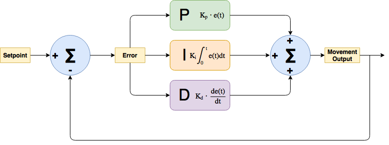
PID Control Loop
Due to the design of the motor controller, precise position control is not available, but precise speed control is. So, a PID loop was developed to control the position of the motor. The PID loop works be measuring the error between the desired position and the current position, then setting the speed of the motor to be the sum of three terms: proportional to error (P), proportional to the integral of the error (I), and proportional to the derivative of the error (D). This forms a second order system which can provide fast response to disturbances (such as external on the motor) and allows the motor to quickly move to the desired location. A second layer of control is added by limiting the maximum speed of the motor. It is safe to assume that the motor will always hit this limit because the error is always very large when changing the target position of the stage. As a result, the motors can be set to move to a target position at a given speed. By stringing a series of motion target commands together, the stage will move along a path with a constant feedrate.
Path Planning
Similar to other CNC machines, paths would be created from GCode commands. GCode is able to provide the coarse paths that would be made mathematically, then the tool would interpolate positions to drive the motors to in discrete steps that are possible to achieve.
The CNC controller handled GCode parsing to create discrete paths. The parser was able to handle the following motion commands:
| GCode | Name | Description | Inputs |
|---|---|---|---|
| G00 | Rapid Positioning | Move each axis at its max speed until it reaches the positionit was trying to reach. Traditionally used to move the bit to astarting location or ending location. | Destination X, Y, Z |
| G01 | Linear Interpolation | Move the tool from the current location to the given location in a linear path between the points by interpolating steps between the positions. | Destination X, Y, Z, Feedrate |
| G02 | Circular Interpolation, Clockwise | Move the tool from the current location to the given location in a clockwise arc from another given center point by interpolating steps along the arc. | Destination X, Y, Z, Feedrate, Radius |
| G03 | Circular Interpolation, Counterclockwise | Move the tool from the current location to the given location in a counterclockwise arc from another given center point by interpolating steps along the arc. | Destination X, Y, Z, Feedrate, Radius |
Paths were interpolated from math by taking discrete points on the line of equal length. These points are then pushed to a queue for the motor controller to use as setpoints for the PID control. The points were given by the following formulas:
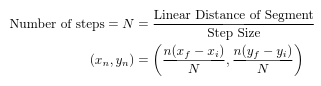
Linear Interpolation for GCode G00, G01

Circular Interpolation for GCode G02, G03

Circular Interpolation Graphic
User Interface
The user interface is a simple serial text console. It currently features three commands: Cycle start, reset, and demo selection. Cycle start will begin running the loaded GCode program. Reset will move the CNC back to its home position and wait for a cycle start command. The demo selection allows the user to load one of the three demo programs pre-loaded onto the machine. Currently, there is no functionality to load GCode programs over serial, but this feature can be trivially implemented.
A command is sent over the serial console as a string with the following format: $[command]<values>. The command field is a character corresponding to the desired command. The values field is an option string of data as required by the command specified. The following table shows the commands available:
| Command | Character | Value Description | Value Type |
|---|---|---|---|
| Cycle Start | c | none | - |
| Reset | r | none | - |
| Demo Select | d | Demo Number (1-3) | int |
Circuits and Hardware
The controller was build with a few pieces of hardware. To the left is a block diagram of the electrical connections within the controller. All that is needed are the stepper motors and encoder for each axis, a limit switch for each axis, and a UART to USB adapter, such as the ones made by FTDI.

Block Diagram
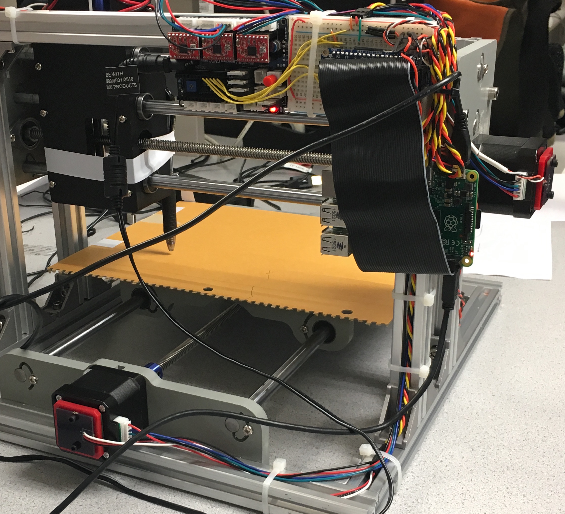
Electronics on CNC Machine
All of the circuits were implemented on a breadboard, but could easily be designed onto a custom PCB shield for the RaspberryPi using EAGLE CAD or Altium.