


![]()
![]()
1
2 3 4
5 6 7
8 9 10
Printable
PDF of this presentation
|
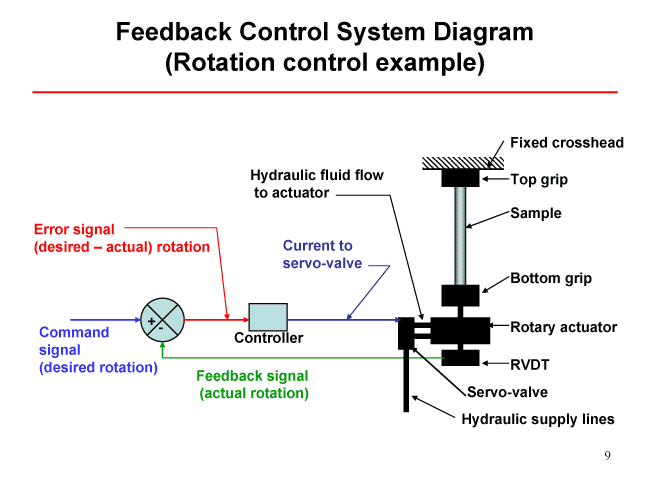
Slide 9 The sketch is a schematic of the machine with a sample gripped between the top grip and the bottom grip. The portion above the top grip shows the fixed crosshead. The RVDT and the hydraulic servo valve are connected to the rotary actuator. The first step is to apply a command signal, in our case a desired rotation. The command signal goes to a comparator where the actual rotation of the machine is compared with the command signal. This generates the error signal. The error signal is the desired rotation subtracted from the actual rotation. The error signal is fed to the controller. The controller then generates a current and sends it to the servo valve. Depending on sign and intensity of the current, the servo valve adjusts the flow of hydraulic fluid to the actuator in order to move the actuator closer to the desired rotation, i.e. to minimize the error signal. |
|
Chalk
Talks Virtual
Tests Test Data Lab Manual |