We used the method of incremental testing throughout our final project. We first tested the functionalities of the software and hardware systems separately, and then tested the entire robot under various scenarios.
Hardware System Testing
We started with making sure that the robot is able to move forward and backward using the two continuous servos. The two servos are calibrated using the script pwm_calibrate.py. Then we let the servos to rotate with full speed in the corresponding directions, and observed whether the robot is moving in a straight line. We found out that the robot tends to turn slightly to the right while it is moving forward. This means that the left servo is spinning faster than the right servo, which is due to a slight calibration inaccuracy. Since it was difficult to achieve precise calibration of both servos by hand, we decided to make software modification instead. So we let the left servo rotate at a speed that is less than the full speed to compensate for the calibration imprecision. The robot is able to move forward and backward relatively straight after this adjustment.
Another major component of the hardware system is the mousetrap ball launcher. We wanted to test that the standard servo has enough power to trigger the mousetrap and the paper ball is shot at the height desirable. We wrote a simple Python script to let the standard servo to rotate approximately 90 degrees, set up the mousetrap, and place the robot ~40cm from the wall. This part of the testing went smoothly, since the ball launcher is quite stable, after we placed the standard servo directly below the mousetrap. Experimentally, we discovered that the closer we place the paper ball to the center of the mousetrap, the lower it will shoot. So we tried to place the ball in a specific location of the mousetrap to make the shooting height relatively consistent.
In addition, we tested the functionality of the camera. It takes pictures of the size 1600x1200 and can save the images in various formats (e.g. png, jpg) as specified. We took a few pictures of the target “Tom” to be used in later testing.
1. Contour Method
For the contour method, we had pictures of completely white background, white background with light grey object, and white background with target “Tom” at the appropriate distance, respectively. We determine the value range corresponding to the shade of grey of target “Tom”. Then we displayed the area of contours found in each image. Eventually, we chose the threshold area to be 1000, because it effectively eliminates the noises in the images.
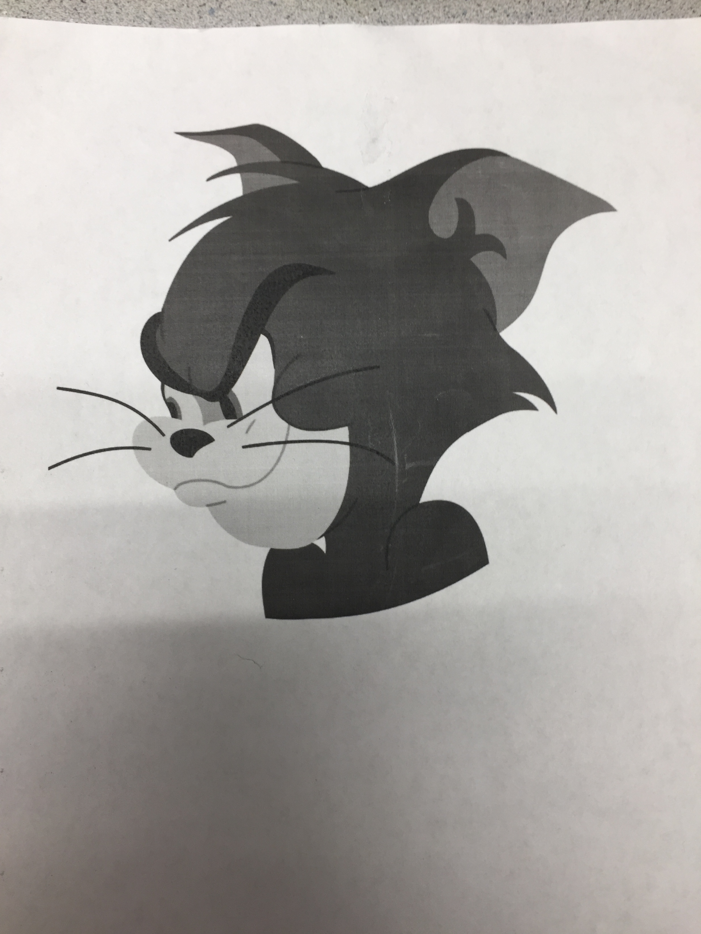

Target "Tom" (left); Light Grey "Jerry" (right)

Fake "Tom"
2. Template Matching Method
For the template matching method, we first cropped the picture of white background with target “Tom” at the appropriate distance to be used as the template image. Then we tested photos of target “Tom” at various locations of the camera view (but kept it at the same distance from the camera). We found out the algorithm is able to identify target “Tom” as long as it is relatively in the center of the image. We verified with photos of “Jerry” and fake “Tom” that the program will not detect them as the target.
On the to other hand, we also put a lot of the time into testing the interface of our program. We first tested on the monitor to ensure that the buttons and the images are displaying at the desired locations. We did exhaustive testing by choosing different set of options and verified that the program would not crash or behave abnormally under any of the situations. Some example scenarios include:
-- Under automatic mode, allow the robot to identify the target and quit on its own
-- Under automatic mode, quit the program when the robot is still searching for target
-- Under manual mode, let the robot move for a while, identify the target and quit on its own
-- Under manual mode, quit the program when the robot is moving
3. Integration Testing
When we were confident that the hardware and software systems functioned on their own, we assembled the entire robot system, and did integration testing. We set up white foam boards along the wall, and put up images of target “Tom”, “Jerry”, and fake “Tom” on the boards at various locations. We focused mainly on testing the automatic mode, because it involves more complicated interactions between the software and hardware. Along the way, we made a few modifications to allow for more stable performance. We replaced the old screws with new 3D-printed ones, which hold our frame together more firmly. We changed the the “mousetrap trigger string” from electrical wire to stiff wires. We screwed two frames for the continuous servos more tightly to the robot, as the two wheels were moving sideways before, making it harder for the robot to travel in a straight line. We also adjusted the height and angle of the camera. We realized that it is useful to make the camera facing slightly towards the rear end of the robot, since the camera is located at the back of the robot and this allowed for more accurate aiming. Finally, we noticed that the fresh batteries are very important, because they directly affected the speed of our servos and our robot could behave abnormally with exhaustive batteries.