Rationale and Source of Project Idea
There was a previous lab session in this course that involved building an autonomous robot on a Raspberry Pi platform and both team members have enjoyed that lab session very much. Therefore, both of us are interested in further extending the functionalities of the robot built in previous lab. In addition, computer vision and robot manipulation have always been trending topics in artificial systems, and both team members are interested in exploring the methods to acquire, process, and analyze digital images using the R-Pi platform. We also wanted to design a fun project idea and build a system that’s cost-friendly and dependable.
The main feature of this project consists of a little moving robot that can be operated both automatically and by a user. The robot will have applications that can control its movement when set to move freely as well as programs that help users to navigate the robot as they wish. In addition, a R-Pi camera will be set up to capture pictures of the robot’s surroundings as it moves. Therefore, an additional feature the robot system is to have programs that analyze these pictures and extract useful information from the pictures. In fact, the little robot will be looking for a pre-specified target image along its way, and once the target is correctly identified, the mousetrap mechanism on the little robot will launch a paper ball toward the target image. In order to increase the fun level of the target identification, we have created “fake” images to “confuse” the robot.
Mathematical Equations
All mathematical equations used will be discussed in detail in the Hardware Design section. The mathematical equations used are relatively straightforward.
Hardware Design

Overall Design Block Diagram
1. Robot Frame
All components needed for the robot are shown in the figure below. One thing to note is that the two servo motors used are the continuous parallax servo motors. The hardware of the little robot ball launcher consists mainly of a R-Pi computer, a piTFT touchscreen, the autonomous robot assembly, a battery pack, a mousetrap and a R-Pi camera. Since we have done a similar robot assembly in a previous lab, we have followed the instructions provided in the lab handout.

Components for Robot Assembly
Following the procedures in lab handout, we first attached the two servo brackets using 4 #3, 16mm screws. Then we attached the 4 wooden stand-offs to the upper frame piece using 4 #3, 8mm screws. However, since we need to insert a protoboard between the the wooden stand-offs and the upper frame piece in the later step, we only attached 3 of the 4 wooden stand-offs. Next, we attached the second level to the frame using 2 #3, 8mm screws. Again, in order to make the later assembly easier, we only added screws to two of the stand-offs. We moved to connect motors to the two brackets using 2 #3, 10mm screws. The next step was to install bearing to the front dowel. Since the ball bearing was already attached to the front dowel, we only needed to connect the whole front dowel to the middle front of the frame using the #3, 10mm screw. Since we also needed to attach battery holders, protoboard, and the R-Pi to our robot, we have used three pieces of adhesive Velcro. We put one piece of Velcro to the underside of the main body for the battery holder, one piece of Velcro to the upper side of the main body for the protoboard and one piece of Velcro to the upper side of the second level for the R-Pi. We have also used a piCamera to capture pictures of the surrounding and connected it to the camera port on the R-Pi. The camera is placed on the left side of the robot. Since our robot is relatively low, we have used two pieces of stiff boards to hold the piCamera higher in the air. At the end, we removed the center screw from the two motors as well as the “horn” that is installed on the servo, placed the wheels on the spline fitting and reattached the center screw. One thing to note is that although we did not have the batteries installed, we have wired a switch for turning on and off the motor power supply so that in case we did place the battery pack there, we did not need to physically remove the battery pack.
2. Continuous Parallax Servo Motors
We have used two continuous parallax servo motors as the wheels for the robot. From the Parallax servo motor datasheet, we see that the period of the square wave when the servo is still is 21.5ms, therefore, we have used a frequency of 1/0.0215Hz in the GPIO.PWM() function. The duty cycle is also different. Since the so-called “on” time of the servo is 1.5ms out of the entire 21.5ms, we have used a duty cycle of 100*1.5/21.5.

Continuous Rotation Servo Communication Protocol (Calibration)
The figure below is a simple circuit diagram from the datasheet for connecting the servo to our R-Pi. It shows that there are three different colors of wires connected the servo. The white wire is connected to the I/O pin on the R-Pi. In this case, the GPIO pin are 13 and 6, respectively. The red wire is connected the positive servo power supply, which is a 5V power supply source. The black wire is connected to the ground of the R-Pi, which also shares the same ground with the 5V power supply. It is important to note that the power supply for R-Pi is a different power supply source for the servo.

Circuit Diagram for Servo and R-Pi Connection
After we connected the servo to the R-Pi as discussed above, we used pwm_calibrate.py to calibrate the servo. The servo has a potentiometer access port right above the place where the cables are attached to the servo case, and this port allows us to adjust the servo. In order to calibrate it, we had the R-Pi sending a 1.5ms pulse width signal to the servo, and we adjusted the potentiometer so that the servo was held completely still. After we were satisfied with the calibration result, we moved on to servo control.
3. Ball Firing Mechanism: the Mousetrap
We have used a simple mousetrap as the ball firing mechanism for our little robot, as shown in the figure below. Originally our team planned to alter the mousetrap so that when the lock pin on the mousetrap is set up, there will be a metal hook that holds the lock pin from firing. Once the orientation of the metal hook is turned, it will no longer hold the lock pin and fire the ball that has been put on the lock pin. However, as we soon discovered, there is a safety issue with the original design since the metal hook we created does not hold the lock pin as tightly as we have hoped for, and sometimes the metal hook will involuntarily release the lock pin and cause unexpected firing of the paper ball.

Ball Launching Machanism
In order to make the ball firing mechanism more stable, we have decided to use the mousetrap the way it is. In order to fire the paper ball at the time we want, we have attached a parallax standard rotation servo motor to the yellow catch using a piece of stiff wire. The servo is configured so that whenever we want to fire the paper ball, it will rotate 90 degrees counterclockwise. The stiff wire will then pull the yellow catch down, causing the lock pin to release the paper ball that has been placed there before. After the ball has been fired, the servo will rotate back 90 degrees in the clockwise direction to its original position. The mousetrap is attached to the end of the robot so we can fit the servo between the two wheels at the back.
Software Design

Software Design Block Diagram
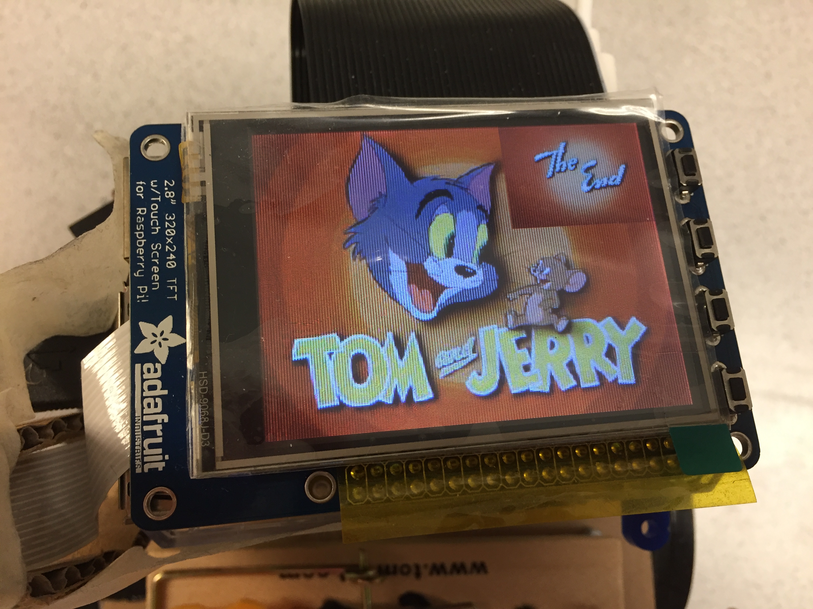
The software controls the movement and user interface for the robot. The figure above shows a high-level software design block diagram. As we can see from the diagram, we have a welcome screen once the user starts the program, two operating modes that can be decided by the user, and an ending screen warning user about the end of the program. We have chosen a theme for our ball launching mission. We have decided that the goal for our little robot is to find the picture of Tom the cat and fire the paper ball at him so that Jerry the mouse can successfully get the cheese cube.
1. User Interface


Welcome Screen (upper left); End Screen (upper right); "Detecting Tom" (lower left); "Happy Jerry" (lower right)
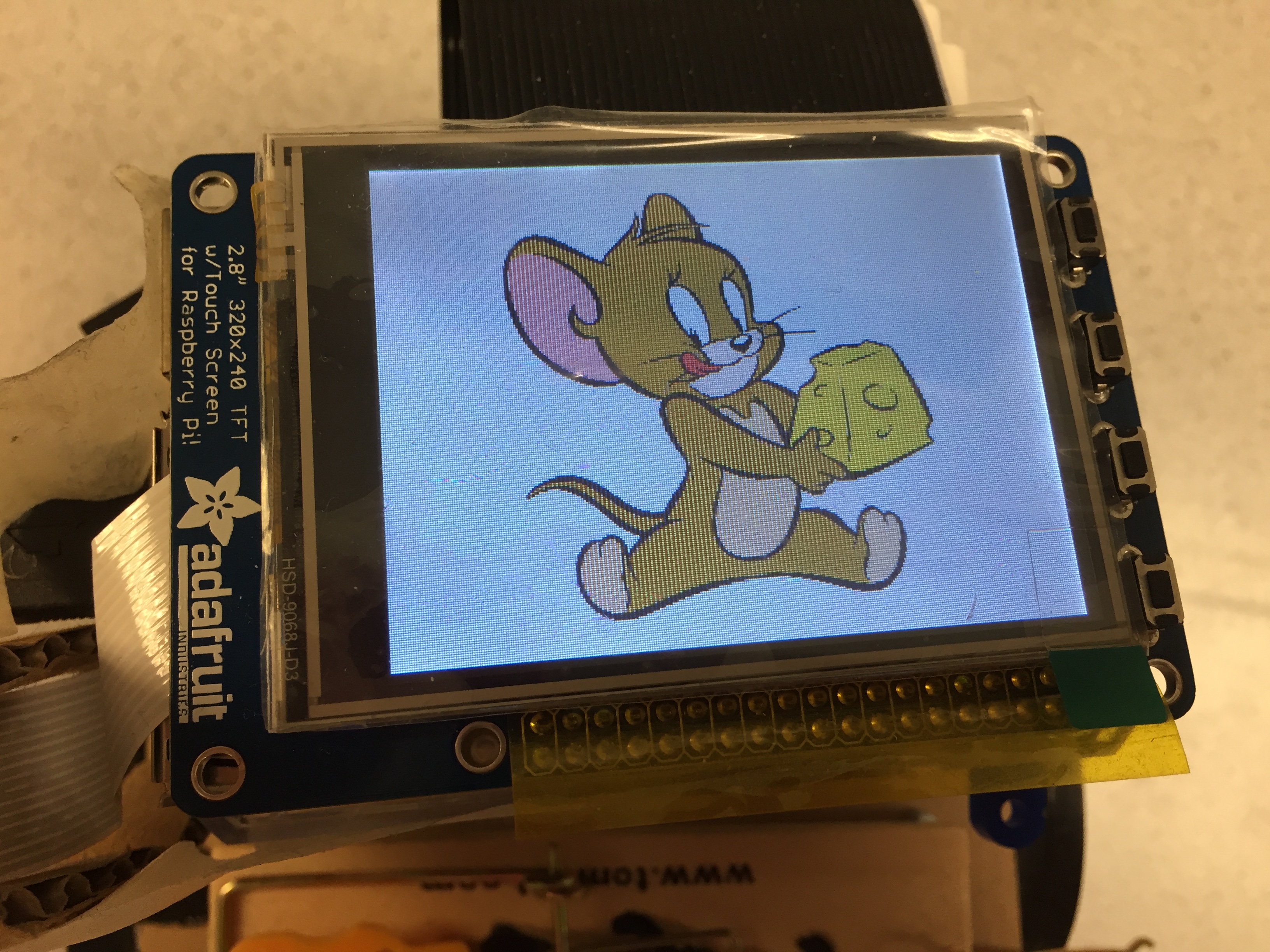
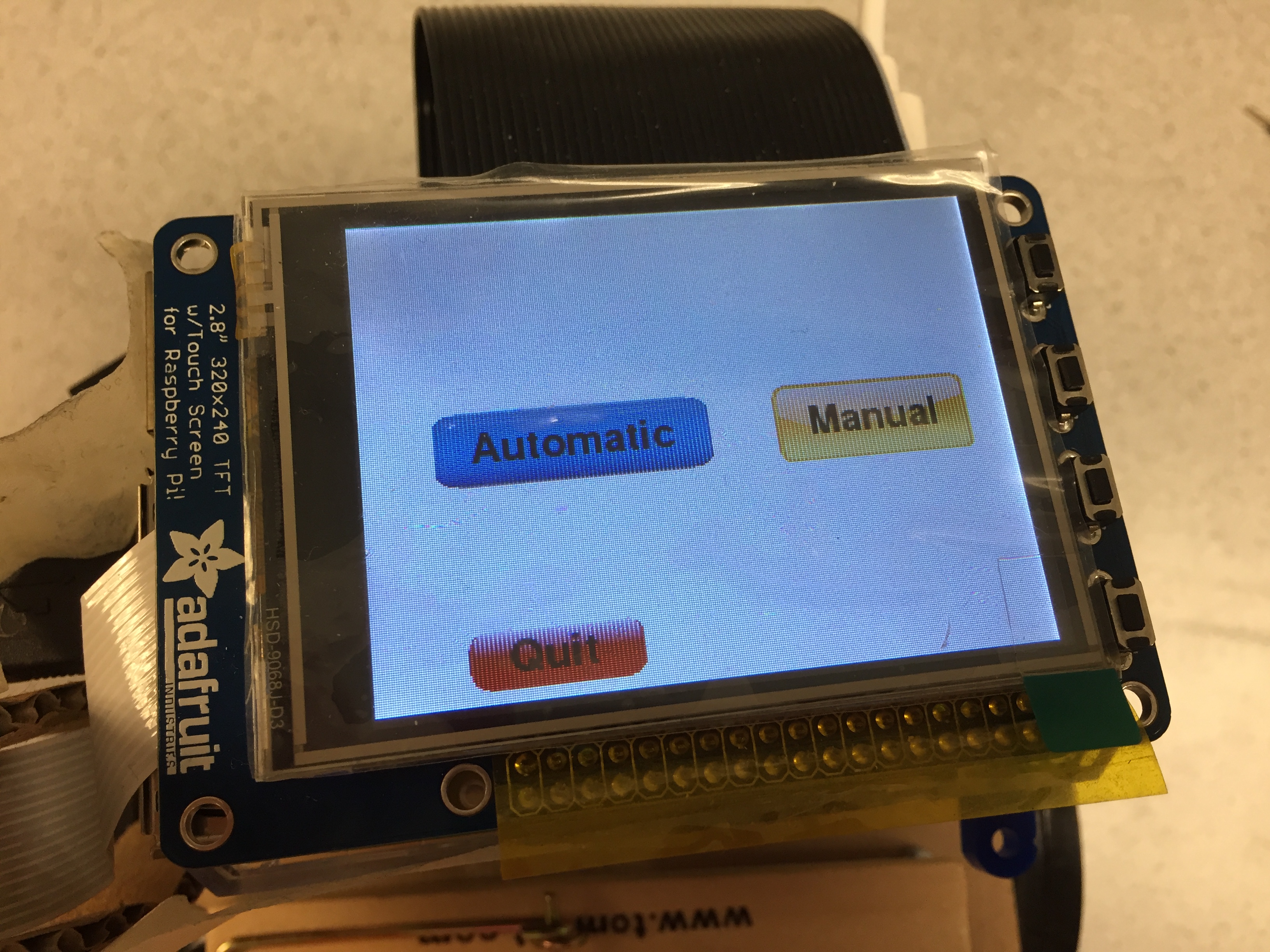
The overall user interface is designed around the Tom and Jerry theme. Upon entering the program, the user will see a picture of Tom and Jerry on the piTFT touchscreen for a brief time before the user can choose the operating mode. The upper left figure above shows the beginning screen when the user starts the program. We have decided on two operating modes: automatic and manual. There is also a quit button at the bottom of the touchscreen so that user can choose to leave the game any time they wish. The figure below shows the display screen for the two operating modes. Once the paper ball has been fired successfully, there will be an ending scene in which a picture with “The End” appears on the piTFT screen. The upper right figure above shows the ending scene. We have also included a piece of theme song from Tom and Jerry in the program so that this theme song will be played throughout the game.
2. Operation Modes
There are two operating modes for the users to choose: automatic and manual.
Mode Selection Screen
Once the user hits the automatic button on the piTFT touchscreen, the robot is programmed to move forward at a full speed. During the automatic mode, there is always a quit button at the bottom of the screen so that the user can choose to exit the game whenever they want. As the robot moves forward, the piCamera will take pictures of the surroundings every 0.5 second. The captured image will then be analyzed to find the area of the dark gray shapes on the image. The OpenCV function findContours() is used to look for the contour of the defined dark gray shapes on the captured image. The returned value from this function is the detected contours. Each contour is stored as a vector of points. Next, we loop through the detected contours and calculate the area of the detected contours. We have defined that if the area of the detected contour is over 1000, it means the target has been identified. However, as we discovered, at the time the program knows it has found the target, the robot may have moved too far to miss the aim. Therefore, we stop the robot and take another picture of the surrounding to confirm whether the target is at the right position for ball firing. For this newly captured picture, we find its dark gray areas and if the dark gray area is too small, we know that the robot has moved too far. In this case, the robot starts to move backward for about a fraction of a second, and the same procedures above will be repeated again until we find that the robot is at the right position of the target. However, if the dark gray area is greater than the threshold we set, we know the target is in the view of the camera, and the robot only needs to adjust its position slightly relatively to the target position. In this case, we have used another function called moments to first calculate the moments of the image and then calculate the center of the dark gray contour. The center of the contour is defined as the division of the m10 moment and m00 moment of the image. If the center of the contour is greater than 1200, the robot is slightly ahead of the target so the robot will move backward for a fraction of a second. If the center of the contour is less than 400, meaning the robot is slightly behind the target, the robot will move forward for a fraction of time. Once the above procedures are repeated until the robot is almost in front of the target, the ball firing mechanism will rotate the standard rotation servo and pull down the yellow catch on the mousetrap to release the paper ball aiming at the target. At the end of the automatic mode after the paper ball is successfully fired, a picture of Jerry the mouse with cheese in its hand will appear on the screen to indicate the mission completion.

Robot Searching for Target in Manual Mode
The other operating mode is the manual mode. Once the user hits the manual button the piTFT touchscreen, a series of direction buttons will appear on the piTFT screen, as shown in the figure below. The user can then choose for the robot to move forward, backward, stop, and aim. The aim button is pressed when the user thinks the robot has moved to a position where the ball firing mechanism is aiming right at the target. Once the aim button is pressed, the piCamera will take a picture of its surrounding at its position. In order to compare whether the robot is at a correct location to fire the paper ball, we have used the matchTemplate() function to compare the captured image with a pre-defined template image. We have taken a front picture of our target and cropped the head section of Tom the cat. The cropped image is then compared with the newly captured image with a threshold. We have used a threshold of 0.6 in this case since the matched locations are only a few if the threshold is too high and the matched locations are too many if the threshold is too low. The matchTemplate() function returns the array of locations where the two images match. If the number of matched locations is reasonably large enough, we say that the robot is at a position where the ball firing mechanism is ready to fire. The user can then hit the aim button again to release the paper ball. However, if the number of matched locations is really small, we consider the matching has failed and a screen with “Keep searching” will appear so the user can re-adjust the robot position. At the end of the manual mode after the paper ball is successfully fired, a picture of Jerry the mouse with cheese in its hand will appear on the screen to indicate the mission completion.

Manual Mode Screen
3. Hardware and Software Tradeoffs
Throughout the project, we had to make changes in both hardware and software so that they both work well for each other and with each other. For example, when we were implementing the motor wheels, we chose the GPIO pin 13 and 6 since they did not have secondary functions that will affect the performance of the robot. Another example is the design of the mousetrap firing mechanism. Originally we thought about using hardware to control the ball firing mechanism. However, we discovered that the method is not very safe and not reliable, so we switched to a new method in which the hardware and software would work together to control the firing. In addition, one of the motor wheels on the robot has a somewhat loose connection, which causes the wheel to move at a slightly different direction and speed than the other wheel. We have tried different screws and electrical tapes to fix the problem, but the solution did not work well. In order to solve this, we have altered the speed for that wheel in the software so that although theoretically the two wheels are moving at different speeds, the loose connection accounts for the speed difference and the two wheels moves at the same speed in practice.