CNPI: Improving CNC performance with a Raspberry Pi
Jay Fetter and Ricardo Stephen
Introduction

A computerized numerical controller or CNC machine is the backbone of a modern day machine shop. A CNC is a computer controlled machine that can programmed to produce a specific part. These are useful in manufacturing when a large copies of a part are needed or when a part contains geometries that are impossible to make with a manual machine.
These machines can range in price from $10k to over $1 million. One of the disparities between a “low end” CNC and a “top of the line” CNC is the accuracy at which it can make different parts. In order to insure the greatest accuracy and precision in part manufacturing, modern CNC’s rely on dynamic feedback from a variety of sensors.
Objective
The goal of this project is to develop a low-cost supplemental add on device to a CNC system to provide similar feedback control like a more expensive machine. This would allows smaller shops to produce higher quality parts, while avoiding the significant expense of upgrading machinery. The final result of this project would be to create a sub $100 easy to use device that can easily be integrated into the machine shop environment.
Design
Machining Background
In order to accomplish our goal of improving performance of “low end” CNC machines, we first had to quantify what we considered good performance. For the scope of this project, we determined that we consider high levels of chatter to be bad performance. Chatter occurs when the machine hits a self-excited level of vibration while machining a part. This can be detrimental to the surface finish of a part, tool life, and the operator's eardrums. There are many ways to reduce chatter, such as using a stiffer setup and better tools.
However, these are parameters that our device cannot control so we sought out other ways to reduce chatter. Other methods of reducing chatter are modifying the feeds and speeds on the machine. The feedrate is defined by how fast the machine will move over the part. The spindle speed is how fast the tool is spinning. Both of these parameters can be set in software and presented an opening that we sought to exploit to reduce chatter.
Hardware
We used an Okuma Cadet V OSP5020m for testing. This machine was available to use for Blue Apron Machinists in the Emerson Machine Shop in Rhodes Hall. Since one of the group members had extensive experience working with this machine, we were able to get access to experiment on the machine without any hiccups.
We also used a standard USB microphone in order to record noise from the mill for chatter detection. The USB microphone was capable of recording frequencies as high as 44.1KHz, the maximum frequency audible by human ears. This was far greater than the application requirement, since chatter frequencies almost always occur below 2KHz.
Lastly, we used two serial cables, two Serial-to-USB adapters and one null modem. This was required because the pi intercepted the serial communication line between the computer and the mill by connecting to the computer and the mill over serial lines and then forwarding messages between the two systems. The Serial-to-USB adapters were used connect the pi to each of the two serial cables - one connecting to the computer and the other to the mill. The null modem was required between the computer and the pi because they both act as serial hosts; the null modem was capable of crossing the Tx and Rx lines and all other host-device line pairs so the computer and the pi would each act as devices to the other. The configuration of the communication system can be seen below:

Software
Microphone and FFT
Setting up the USB microphone first consisted of installing the proper libraries to interface with the USB microphone. First, the ALSA sound API was installed to allow python programs to more easily interface with sound cards. Then, pyaudio and portaudio (a dependency for pyaudio) were installed; pyaudio was then used to to read from the microphone using python. Additionally, python’s wave module was used to write this audio data to .wav files.
To test the USB microphone’s functionality, simple python scripts were written to use pyaudio to record audio and then write the data to .wav files. These scripts were successfully tested by recording arbitrary sounds.
Then, the audio recording was easily transformed into a spectrogram using the specgram method in pylab. A sample spectrogram can be found below:

CNC Communication

Using the Pi as the go-between.
Our first milestone was determining how to communicate with the CNC via RS-232. The software aspect of this simply consisted of using the pySerial library to write python scripts that could easily read and write from serial ports. For initial testing, we used a laptop to read the initial file request send from the CNC mill over serial. A Diablo High Speed USB to DB0 Serial Adapter (not in the parts list since this was only for testing) was connected to the laptop’s USB port, and then to the CNC mill via a serial cable. However, we were unable to read meaningful information over the serial port because the USB-serial adapter did not have the hardware required to implement any flow serial flow control, which was required for proper communication with the CNC.
After the initial failed attempts, new USB-serial adapters with the FTDI chips required for serial flow control were acquired and used for testing. Even with the new FTDI chips, testing was required to determine the proper serial parameters used by the CNC mill. Further testing yielded in the following parameters:
- 9600 bps
- Software flow control enabled
- Hardware flow control disabled
- Even parity
- 7-bit data size
- 2 stop bits
Once the parameters were acquired, it was possible to connect the pi as shown in FIGURE777 and proceed with testing. Then, using the We were able to send a program request from the CNC, capture that transmission on the pi, and then forward that transmission to the CNC computer. The CNC computer then proceeded to dripfeed the GCode program via serial through our pi, which passed it to the CNC. The CNC was actually able to receive the program and run properly. (Our hands were over the emergency stop on the machine the entire time this was happening.)
GCode Parsing
An important part of our project was the parsing of GCode files to be run on the CNC. This would allow us to visualize what the machine was working on and allow us to map areas of high chatter to locations on the part. In order to accomplish this task, a GCode parser was written in python. The parser is designed to keep track of important global information like the current position, feedrate, tool number, and spindle speed.
CNC Machine Timing
The CNC machine posed a major problem while we were testing. An important part of our process was mapping noise levels received to a specific instruction. However, due to the way the CNC operates, there is no real way to know exactly which instruction is being executed at any point in time. This happens because the CNC machine buffers instructions so when the Pi would send an instruction, it doesn’t mean that the CNC is currently executing that instruction. This buffering helps the machine operate by making the transitions between instructions much smoother, but hurts the scope of our project.
In order to get around this problem, we calculated the time it would take for each instruction to execute and attempted to map the time at which we experienced high noise to what instruction the Pi thought it was executing at that time. These timing calculations were embedded into the GCode parser.
Plotting
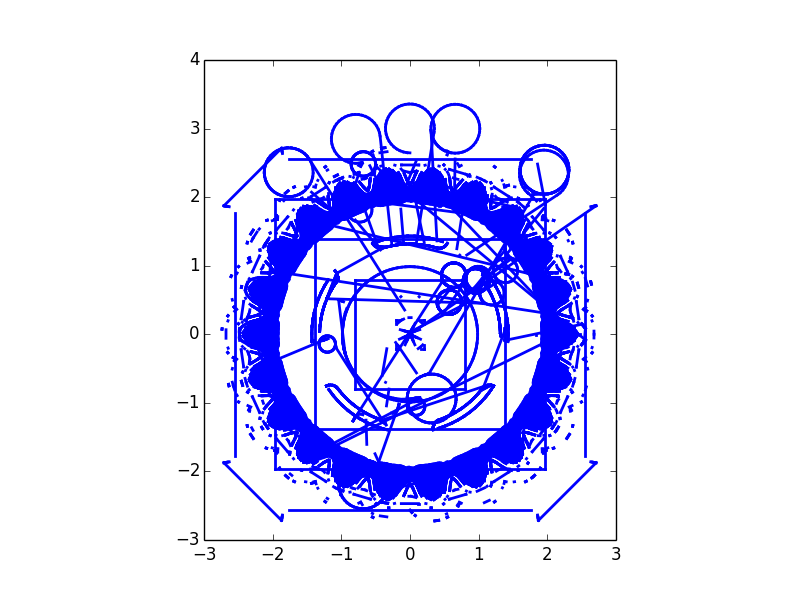
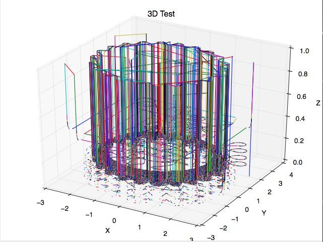
An important part of our project was generating a visual from the provided gcode. This allows the machinist to visualize areas that are prone to high noise. This also allows the visualization of how the noise profile changes as the part is machined.
In order to create a plot of the part being machined, the GCode parser was leveraged as well as the MatPlotLib library for python. We were able to take the parameters maintained by the parser and use them to create 3D plots of the parts being machined. This was not as simple as it sounds because these GCode programs are so long that we would be plotting 40,000+ lines per program. This was an intense memory and CPU overhead for the Pi. This was something that required a lot of testing and tuning, because there are many different ways this library works and each of them provide different performance. We were able to eventually fine tune our approach and achieve 100x speedup in our plotting compared to when we started. Microphone and FFT Recompiling
Demo
Testing
GCode Parser
The parser was tested with various GCode programs provided by the Cornell Baja SAE and Resistance Racing: Cornell Electric Motorcycle project teams. These programs were considered good candidates because they were quite long (~50,000 lines) and were all parts that we had access to the CADs of to check our visualization against.
CNC Machine
The CNC machine posed a major problem while we were testing. An important part of our process was mapping noise levels received to a specific instruction. However, due to the way the CNC operates, there is no real way to know exactly which instruction is being executed at any point in time. This happens because the CNC machine buffers instructions so when the Pi would send an instruction, it doesn’t mean that the CNC is currently executing that instruction. This buffering helps the machine operate by making the transitions between instructions much smoother, but hurts the scope of our project.
In order to get around this problem, we calculated the time it would take for each instruction to execute and attempted to map the time at which we experienced high noise to what instruction the Pi thought it was executing at that time.
Drawings


Results
Our final system that we designed was able to accomplish all of the milestones that we sought out to achieve. We built a fully functional GCode Parser, inserted the Raspberry Pi into the communication loop, were able to plot GCode programs, and use a microphone and fft for noise detection. All of our subsystems for the project worked properly.
However, there was a major design flaw that were not able to overcome: The inability to determine which instruction the CNC machine is executing. This flaw prevented us from confidently recompiling the program to modulate the feeds and speeds to reduce chatter.
Conclusion
This project was an experience. We were able to accomplish all of our subsystems, but were held up with unexpected difficulty with the CNC machine itself. We were able to communicate with the CNC without using a licensed Direct Numerical Control software package. In essence, we removed the CNC computer from the equation entirely which is pretty cool. So in conclusion, we are very happy with what we were able to accomplish with this project and how it turned out.
Future Work
In the future it would be useful to take this system and figure out a good way to recompiling the GCode on the fly. After talking with some of the Emerson Machine Shop Staff, there are some very hacky avenues we can attempt using the CNC and how it operates. We also believe that with more testing, we can finetune our timing estimation and add in sync points to the program to help it keep track of what code is executing. Another avenue would be to have the Pi interact with the manual overrides on the machine and modulate the feeds and speeds that way. We discouraged this approach because it would not allow the user to recompile the program with better feeds and speeds.
Another avenue we wish to explore would be reatime plotting as instructions are being executed. This would be a very cool feature for an operator to have so they can know how far along a part is in case they cannot view the part.
The Pi is also a very good platform for creating a DNC computer. It is small, cheap, and does everything you would want that computer to be doing, plus has the ability to be easily be expanded upon. Our current project removes the existing computer from the Emerson machine shop and with a little touching up on the UI, can be just as configurable.
We would also like to develop a waterproof/shockproof case for the Pi to make sure it stays safe when it is in the machine shop environment.
Division of Labor
Jay worked on the Gcode-Parsing and dealing with the CNC. Also, started the fft code. Worked on the Website and the report.
Ricardo worked on the microphone and the serial communication. Also, worked on integrating everything as well as the Website and report.
Cost Analysis
| Part |
Source |
Quanity | Cost |
|---|---|---|---|
| Raspberry Pi |
http://www.mcmelectronics.com/product/83-16530 | 1 | $35 |
| Cable | http://www.amazon.com/InstallerParts-Male-Female-Serial-Cable/dp/B008NCC85C | 2 | $5 |
| Null Modem |
http://www.amazon.com/StarTech-RS232-Serial-Modem-Adapter/dp/B000DZH4V0 | 1 | $3 |
| Serial-USB Adapter | http://www.amazon.com/Chipset-Speed-Serial-RS-232-Converter/dp/B005S72HHO | 2 | $14 |
| Microphone | http://www.amazon.com/Adjustable-Microphone-Compatible-Chatting-Recording/dp/B00UZY2YQE | 1 | $8 |
| Total Cost |
$84 |
Code Appendix
1 2 3 4 5 6 7 8 9 10 11 12 13 14 15 16 17 18 19 20 21 22 23 24 25 26 27 28 29 30 31 32 33 34 35 36 37 38 39 40 41 42 43 44 45 46 47 48 | #!/usr/local/bin/python3 # http://stackoverflow.com/questions/10733903/pyaudio-input-overflowed import pyaudio import wave import time CHUNK = 2**12 FORMAT=pyaudio.paInt16 CHANNELS = 1 RATE = 44100 RECORD_SECONDS = 5 TIMESTAMP = str(int(time.time())) WAVE_OUTPUT_FILENAME = "audio/async"+TIMESTAMP+".wav" wf = wave.open(WAVE_OUTPUT_FILENAME, 'wb') wf.setnchannels(CHANNELS) wf.setsampwidth(2) wf.setframerate(RATE) end_signal = 0 def callback(in_data, frame_count, time_info, status): global end_signal print("Callback") wf.writeframes(in_data) if(end_signal == 1): wf.close() exit() else: return(in_data, pyaudio.paContinue) p=pyaudio.PyAudio() inStream = p.open(format = FORMAT, channels=CHANNELS, rate=RATE, input=True, output=True, frames_per_buffer=CHUNK, stream_callback=callback) while True: try: continue except KeyboardInterrupt: end_signal = 1 |
pyaudio_asynch.py
1 2 3 4 5 6 7 8 9 10 11 12 13 14 15 16 17 18 19 20 21 22 23 24 25 26 27 28 29 30 31 32 33 34 35 36 37 38 39 40 | import pyaudio import wave import time CHUNK = 2000 FORMAT = pyaudio.paInt16 CHANNELS = 1 RATE = 2000 RECORD_SECONDS = 5 TIMESTAMP = str(int(time.time())) WAVE_OUTPUT_FILENAME = "audio/output"+TIMESTAMP+".wav" p = pyaudio.PyAudio() stream = p.open(format=FORMAT, channels=CHANNELS, rate=RATE, input=True, frames_per_buffer=CHUNK) print("* recording") frames = [] for i in range(0, int(RATE / CHUNK * RECORD_SECONDS)): data = stream.read(CHUNK) frames.append(data) print("* done recording") stream.stop_stream() stream.close() p.terminate() wf = wave.open(WAVE_OUTPUT_FILENAME, 'wb') wf.setnchannels(CHANNELS) wf.setsampwidth(p.get_sample_size(FORMAT)) wf.setframerate(RATE) wf.writeframes(b''.join(frames)) wf.close() |
pyaudio_record.py
1 2 3 4 5 6 7 8 9 10 11 12 13 14 15 16 17 18 19 20 21 22 23 24 25 26 27 28 29 30 31 32 33 34 35 | #http://glowingpython.blogspot.ro/2011/08/how-to-plot-frequency-spectrum-with.html from pylab import plot, show, title, xlabel, ylabel, subplot, savefig from scipy import fft, arange, ifft from numpy import sin, linspace, pi from scipy.io.wavfile import read,write def plotSpectru(y,Fs): n = len(y) # lungime semnal k = arange(n) T = n/Fs frq = k/T # two sides frequency range frq = frq[range(n/2)] # one side frequency range Y = fft(y)/n # fft computing and normalization Y = Y[range(n/2)] plot(frq,abs(Y),'r') # plotting the spectrum xlabel('Freq (Hz)') ylabel('|Y(freq)|') Fs,data=read('audio/test2.wav') y=data[:,1] lungime=len(y) timp=len(y)/Fs t=linspace(0,timp,len(y)) subplot(2,1,1) plot(t,y) xlabel('Time') ylabel('Amplitude') subplot(2,1,2) plotSpectru(y,Fs) show() |
cnc_fft.py
1 2 3 4 5 6 7 8 9 10 11 12 13 14 15 16 17 18 19 20 21 22 23 24 25 26 27 28 29 30 31 32 33 34 35 36 37 38 39 40 41 42 43 44 45 46 47 48 49 50 51 52 53 54 55 56 57 58 59 60 61 62 63 64 65 66 67 68 69 70 71 72 73 74 75 76 77 78 79 80 81 82 83 84 85 86 87 88 89 90 91 92 93 94 95 96 97 98 99 100 101 102 103 104 105 106 107 108 109 110 111 112 113 114 115 116 117 118 119 120 121 122 123 124 125 126 127 128 129 130 131 132 133 134 135 136 137 138 139 140 141 142 143 144 145 146 147 148 149 150 151 152 153 154 155 156 157 158 159 160 161 162 163 164 165 166 167 168 169 170 171 172 173 174 175 176 177 178 179 180 181 182 183 184 185 186 187 188 189 190 191 192 193 194 195 196 197 198 199 200 201 202 203 204 205 206 207 208 209 210 211 212 213 214 215 216 217 218 219 220 221 222 223 224 225 226 227 228 229 230 231 232 233 234 235 236 237 238 239 240 241 242 243 244 245 246 247 248 249 250 251 252 253 254 255 256 257 258 259 260 261 262 263 264 265 266 267 268 269 270 271 272 273 274 275 276 277 278 279 280 281 282 283 284 285 286 287 288 289 290 291 292 293 294 295 296 297 298 299 300 301 302 303 304 305 306 307 308 309 310 311 312 313 314 315 316 317 | #!/usr/bin/python # This is the main gcode parser for the project. # Rev. 1.0 will take in static Gcode files and parse them # Rev. 2.0 will take in the Gcode dynamically via Serial # import sys, fileinput, math, re # -*- coding: utf-8 -*- import numpy as np import matplotlib import matplotlib.pyplot as plt import matplotlib.patches as mpatches import mpl_toolkits.mplot3d.axes3d as p3 import matplotlib.animation as animation from matplotlib import cm, colors, patches prevX = float(0.0) prevY = float(0.0) prevZ = float(0.0) globalX = float(0.0) globalY = float(0.0) globalZ = float(0.0) globalI = float(0.0) globalJ = float(0.0) feedRate = 0 spindleSpeed = 0 toolNum = 19 toolSize = 0 rapid = 100 toolChangeTime = 5/60 def parseM(line, index): index += 1 return index def parseX(line, index): global globalX if(not line[index][0] == 'X'): exit(1) prevX = globalX globalX = float(line[index][1:]) #print("Parsing X: %f\n") % globalX index += 1 return index def parseY(line, index): global globalY if(not line[index][0] == 'Y'): exit(1) prevY = globalY globalY = float(line[index][1:]) #print("Parsing Y: %f\n") % globalY index += 1 return index def parseZ(line, index): global globalZ if(not line[index][0] == 'Z'): exit(1) prevZ = globalZ globalZ = float(line[index][1:]) #print("Parsing Z: %f\n") % globalZ index += 1 return index def parseI(line, index): global globalI if(not line[index][0] == 'I'): exit(1) globalI = float(line[index][1:]) #print("Parsing Z: %f\n") % globalZ index += 1 return index def parseJ(line, index): global globalJ if(not line[index][0] == 'J'): exit(1) globalJ = float(line[index][1:]) #print("Parsing Z: %f\n") % globalZ index += 1 return index def parseG0(line, index): while(index < len(line) and not (line[index] in validCmds)): index = validDirections[line[index][0]](line, index) return index def parseG1(line, index): while(index < len(line) and not (line[index][0] in validCmds)): index = validDirections[line[index][0]](line, index) return index #Circular Move CCW def parseG2(line, index): while(index < len(line) and not (line[index][0] in validCmds)): index = validDirections[line[index][0]](line, index) return index #Circular Move CW: IJ=centerpoint, XY = endpoints def parseG3(line, index): while(index < len(line) and not (line[index][0] in validCmds)): index = validDirections[line[index][0]](line, index) return index def parseG(line, index): global movementType #print("Found a valid G cmd: %s. Index: %d\n") % (line, index) if(not line[index][0] == 'G'): exit(1) index += 1 if(line[index-1] in validGCmds): movementType = line[index-1] index = validGCmds[line[index-1]](line, index) return index def parseT(line, index): global toolNum if(not line[index][0] == 'T'): exit(1) if(len(line[index]) == 1): toolNum = int(line[index+1]) index += 2 else: toolNum = int(line[index][1:]) index += 1 return index #assume its in the format for now: S##### def parseSpindle(line, index): global spindleSpeed #print("Found a valid spindle: Here is the line: %s\n") % line #If this happens, throw an error if(not line[index][0] == 'S'): exit(1) if(len(line[index]) == 1): spindleSpeed = int(line[index+1]) index += 2 else: spindleSpeed = int(line[index][1:]) index += 1 #print("Here is the new spindleSpeed: %s\n") % spindleSpeed return index def parseFeed(line, index): global feedRate #print("Found a valid feedRate: Here is the line: %s\n") % line if(not line[index][0] == 'F'): exit(1) if(len(line[index]) == 1): feedRate = float(line[index+1]) index += 2 else: feedRate = float(line[index][1:]) index += 1 return index def parseComment(line, index): #print("Found a comment: %s\n") % line[index:] i = index while ( i < len(line)): i += 1 if ')' in line[i-1]: #print("Found end of the comment: %s\n") % line[i-1] return i validCmds = {'G':parseG, 'M':parseM, 'T':parseT, 'S':parseSpindle, 'F':parseFeed, '(': parseComment} validDirections = {'X': parseX, 'Y':parseY, 'Z': parseZ, 'I': parseI, 'J':parseJ} validGCmds = { 'G00':parseG0, 'G0': parseG0, 'G01':parseG1, 'G1':parseG1, 'G02':parseG2, 'G2':parseG2, 'G03':parseG3, 'G3':parseG3} ''' validMCmds = { 'M03':parseM3, 'M3': parseM3, 'M05':parseM5, 'M5':parseM5, 'M06':parseM6, 'M6':parseM6, 'M08':parseM8, 'M8':parseM8} ''' #Movement Type: #Sticks with whatever the last movement type was #So if the last command to specify movement was g1 #Then an X____Y____ will really mean: G1 X______Y_____ movementType = '' def parseLine(line): i = 0 while( i < len(line)): #print("This is the index Value: %d\n") % i a = str(line[i][0]).split()[0] #print("a: %s\n") % a if( a in validCmds): #print("Is a valid cmd: %s\n") % a i = validCmds[a](line,i) elif( a[0] in validDirections and re.match(r"^([-]?\d+\.?\d+)$",line[i][1:]) is not None): i = validGCmds[movementType](line,i) else: i += 1 plot_scale = 1 def calc_line(x1, y1, x2, y2): if(x2 - x1 == 0): slope = float("inf") else: slope = (y2-y1)/(x2-x1) intercept = y2 - slope*x2 return (slope, intercept) #returns the distance between point 1 and point 2 def calcDistance(x1, y1, z1, x2, y2, z2): global plot_scale return math.sqrt((x2-x1)**2 + (y2-y1)**2 + (z2-z1)**2) def calcTime(distance, feedRate): if(feedRate == 0): return 0 return distance/feedRate def point_under(point, line): slope, intercept = line if(slope != float("inf")): return point[0]*slope + intercept > point[1] else: return point[0] < intercept def point_over(point, line): slope, intercept = line if(slope != float("inf")): return point[0]*slope + intercept < point[1] else: return point[0] > intercept def law_of_cosines(A_X, A_Y, B_X, B_Y, C_X, C_Y): #CNC doesn't do 3D arcs a = calcDistance(B_X, B_Y, 0, C_X, C_Y, 0) b = calcDistance(A_X, A_Y, 0, C_X, C_Y, 0) c = calcDistance(A_X, A_Y, 0, B_X, B_Y, 0) angle = math.acos((b*b+ b*b - a*a)/(2*b*b)) if(point_over([B_X, B_Y], calc_line(C_X, C_Y, A_X, A_Y))): angle = 2*math.pi-angle return (angle,angle*b) def drawArc(): global globalX, globalY, globalZ, globalI, globalJ, prevX, prevY center = [prevX + globalI, prevY+globalJ] radius = calcDistance(globalX, globalY, globalZ, center[0], center[1], prevZ) (angle, length) = law_of_cosines(center[0], center[1], globalX, globalY, prevX, prevY) #Slope is just really globalJ/globalY return (center, radius, angle, length) def parseFile(fileName): with open(fileName) as file: global plot_scale global globalX, globalY, globalZ, globalI, globalJ, feedRate, spindleSpeed, toolNum, toolSize, rapid global prevX, prevY, prevZ total_time = 0 lineNum = 0 text = '' count = 0 add = '' prevTool = 19 first_time = 1 arcs = [] lines = [] fig = plt.figure() ax = p3.Axes3D(fig) for line in file: lineNum += 1 gcode = line.upper().split() parseLine(gcode) time = 0 local_feed = feedRate distance = 0 if(movementType == 'G02' or movementType == 'G2'): center, radius, angle, length = drawArc() distance = length arcs.append(((globalX,globalY,globalZ),(prevX,prevY,prevZ),radius)) elif(movementType == 'G03' or movementType == 'G3'): center, radius, angle, length = drawArc() distance = length arcs.append(((prevX,prevY,prevZ),(globalX, globalY, globalZ), radius)) elif(movementType == 'G00' or movementType == 'G0'): distance = calcDistance(globalX, globalY, globalZ, prevX, prevY, prevZ) lines.append(((prevX, prevY, prevZ), (globalX, globalY, globalZ))) local_feed = rapid line1 = [(prevX, prevY), (globalX, globalY)] (line1_xs, line1_ys) = zip(*line1) if(first_time == 0): ax.plot((prevX, globalX), (prevY, globalY), (prevZ, globalZ)) else: first_time -= 1 elif(movementType == 'G01' or movementType == 'G1'): distance = calcDistance(globalX, globalY, globalZ, prevX, prevY, prevZ) lines.append(((prevX, prevY, prevZ), (globalX, globalY, globalZ))) line1 = [(prevX, prevY), (globalX, globalY)] (line1_xs, line1_ys) = zip(*line1) if(first_time == 0): ax.plot((prevX, globalX), (prevY, globalY), (prevZ, globalZ)) else: first_time -= 1 if(prevTool != toolNum): total_time += toolChangeTime prevTool = toolNum time = calcTime(distance, local_feed) total_time += time prevX = globalX prevY = globalY prevZ = globalZ ax.set_xlabel('X') ax.set_ylabel('Y') ax.set_zlabel('Z') ax.set_title('3D Test') plt.show() parseFile(str(sys.argv[1])) |
gcode_parser.py
Github Repo (Most up-to-date code)
Contact
Jay Fetter
jdf258@cornell.edu
Ricardo Stephen
rls454@cornell.edu