Whiteboard Plotter
Curran Sinha (cs886) and Keshav Varma (kdv8)
Introduction
When given the chance to choose our own final project, we were keen on incorporating a physical hardware component. While brainstorming ideas we stumbled upon a video on YouTube that grabbed our interest. We thought it would be interesting and challenging to attempt to build something similar, so we decided to make a 2D whiteboard plotter. This involved designing, laser cutting and putting together an assembly that could control the position of a pen using two stepper motors, some string, and sheet plastic. Along with that, we developed software to convert images into points and linearly interpolate between them to create a smooth drawing of the original image.
We'd like to thank Prof. Skovira and the TAs for help throughout the course and with getting our final project working.
Objective
Design and implement a 2D whiteboard plotter that can draw images using a whiteboard marker.
Design
Hardware
We started by designing the hardware we would need for the project since we expected the fabrication process would take some time. Since we only had access to a limited number of resources, we decided to construct everything out of 4mm acrylic sheets that could be laser cut on campus by Cornell’s Rapid Prototyping Lab. Using the hardware in the video as inspiration, we designed motor mounts and a gondola to hold the marker in SolidWorks. The use of CAD tools made it easy to rapidly iterate on different spacing.
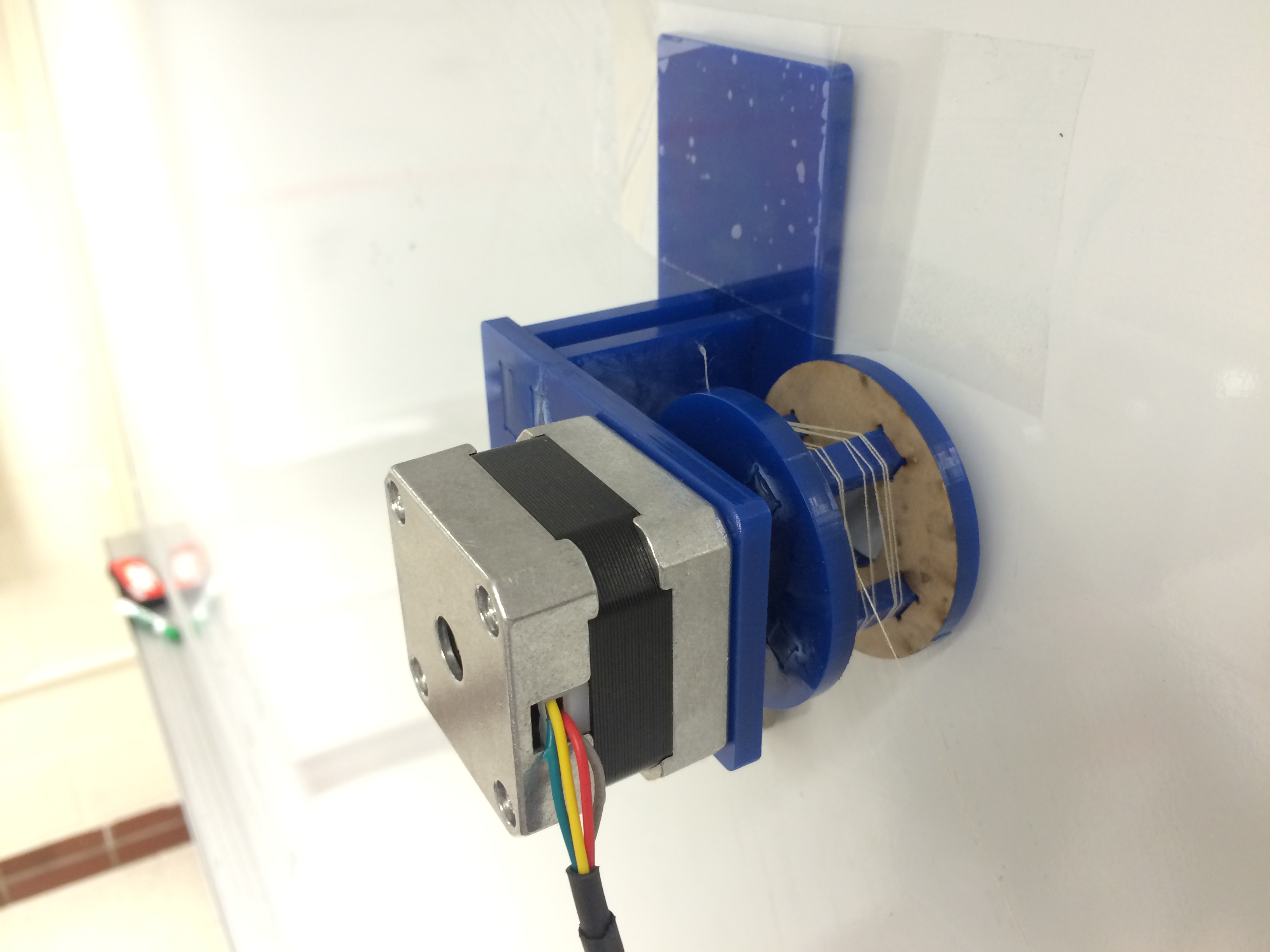
Each motor mount holds a single stepper motor facing the wall in order to keep the motor shaft as close to the drawing surface as possible. The motors we selected are NEMA 17 stepper motors available from Adafruit. Note that stepper motors are required for this application in order to achieve reasonable accuracy. The pulleys are made of small acrylic blocks that are cut and glued in corresponding slots to make a 3D object. The motor mounts are symmetric, allowing us to use the same parts to construct either side.
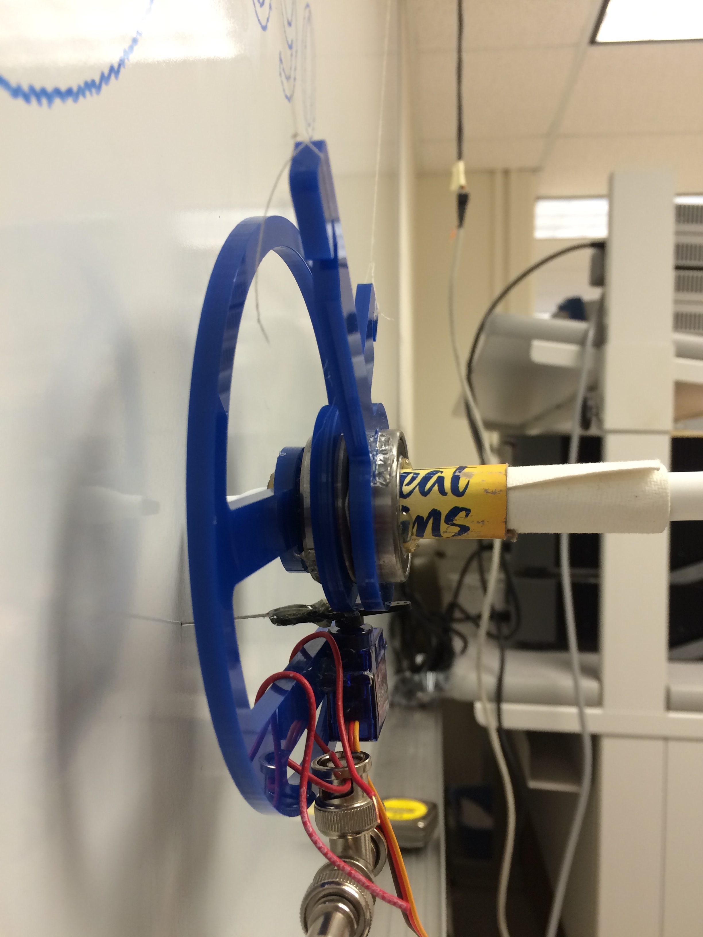
The gondola, shown below, consists of two ball bearings that allow the two strings that hold up the gondola to rotate independently of each other. This is required since the angle between them varies as the position of the gondola changes on the drawing surface. A large balancing plate is used to prevent the entire assembly from rotating with respect to the whiteboard. A single micro servo, also from Adafruit, is used to push the entire gondola away from the whiteboard surface, allowing us to draw unconnected shapes.
The complete CAD files and drawings are available here.
Software
A main goal of the project was to explore the advantages of using a Raspberry Pi in applications that traditionally require a microcontroller for real-time guarantees. We thought our project would be a great fit for the Raspberry Pi 2 Model B as our project doesn’t have extreme real-time requirements and it would allow us to focus on developing the code in Python instead of a lower level language. Since Python is generally a much more productive language, this was extremely beneficial as it allowed us to experiment with different algorithms quickly.
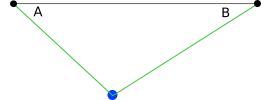
The basic principle of our project involved converting x, y coordinates to lengths of the strings holding the gondola. The only things we input to our code is the distance between the two motors, and the starting distances of each of strings. We use that initial location as the origin (0, 0) point. The first step is to calculate the position of each of the motors relative to the origin. To do this we used GOOD OLD Law of Cosines. For those of you who need a refresher, the law of cosines can be used to calculate the angles of a triangle given the length of the three sides:
Using the standard math library provided by python we were able to calculate the angles A and B (shown below) and in turn were able to calculate the x and y coordinates of the motors using basic trig functions.
After obtaining these points, calculating the lengths of the strings given a point is trivial: we use the distance formula from the point to each motor. The harder part of the algorithm was calculate the linear interpolation between the points. To do this, we calculate the number of ticks each motor needs to perform given its current position and a desired position. We then use the ratio between the number of ticks each motor needs to perform to move each at an appropriate time. The code that performs this is shown below:
In the code, we perform a fixed number of iterations based on the maximum number of ticks that must be performed. Within each iteration, we check if each motor should move during this iteration and perform the necessary operation. This algorithm creates a decent linear interpolation because the distance per tick was very small so the resulting line looks smooth. To further improve it, we break up each line segment into smaller 10 mm segments. During testing, this implementation created an even smoother linear interpolation as each single line segment is relatively small, which helped avoid drawing slightly curved lines.
With our algorithm completed, our next step was to be able to generate a list of shapes to draw. We decided to support the well-established G-code programming language which is commonly used to control CNC machines. Thanks to the format’s popularity, many libraries have already been developed by the hobbyist 3D-printing and laser-cutting community that enable conversion of images to G-code commands. We used the svgmill library to convert SVG images into G-code commands that ca interpreted by our control software. Since our software only handles linear interpolation, complex shapes like circles and curves are decomposed into many smaller line segments by the library. The G-code output is written to a file and read in by plotter.py during execution.
Simulator
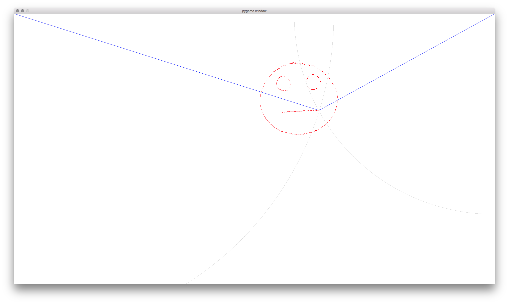
Before we had all the hardware built, we wanted to start testing our drawing algorithm. To enable this, we wrote a simulator using Pygame to model the physical hardware. The simulator, shown below, calculates the intersection of two circles, which represents the simulated position of the gondola. The radius of each circle represents the length of each string. Thus, individual steps of a motor simply change the radius of the corresponding circle.
In order to make our controller code interoperable with both the simulator and the physical implementation, we take advantage of a RPC (remote procedure call) library that allows us to execute functions across the network. When testing with the simulator, our tick() function simply changes the radius of a circle in Pygame, but when using the real implementation, the tick() function would cause the stepper motor driver to send a real pulse. By using the RPC interface, our code remains identical apart from a single command line flag that sets the remote RPC server.
Stepper Motor Driver
With the simulator and algorithm working along with the completed hardware, we then attempted to control the stepper motors from Python. To do this, we use Adafruit’s stepper motor library, provided with the stepper motor HAT. This library exposes a simple interface to control up to two stepper motors. We also hooked up the pen control servo to pin 22 and used software PWM to control the pen’s position. With this completed, we could begin testing the entire implementation.
Bill of Materials
The following list consists of all the parts required for the project excluding the Raspberry Pi 2.
| Part | Supplier | Quantity | Cost | Total |
|---|---|---|---|---|
| Stepper Motor | Adafruit | 2 | $14 | $28 |
| Stepper Motor HAT | Adafruit | 1 | $22.50 | $22.50 |
| 6003-2RS Bearings | Amazon | 2 | $4.40 | $8.80 |
| 12”x12” 4mm Acrylic Sheet | Prof. Skovira | 1 | ~$10 | $10 |
| Micro servo | Adafruit | 1 | $5.95 | $5.95 |
| Universal Mounting Hub | Sparkfun | 1 | $7.49 | $7.49 |
| $82.74 |
Testing
Throughout this project we ran into small issues while building the hardware and software. While assembling the hardware we realized we did not leave enough clearance for a screwdriver to reach the motors with the pulley in place. Thankfully, we were able to use pliers to assemble the motor mounts and did not end up remaking the mounts.
While testing the algorithm, we experimented with different stepping modes provided by the Adafruit library: single, double, microsteps, and interleaved. Each of these modes have different tradeoffs in terms of speed and torque. In single stepping mode, a single motor coil is activated at a time. This results in lower power usage but lower torque. In double stepping mode, two opposite coils are activated, resulting in double the torque but also double the power requirement. Microstepping attempts to use PWM to slowly enter and exit steps to result in smoother motion but results in a much lower overall speed. Interleaved mode switches between single and double stepping modes to reduce average power consumption. We found that we had to use the double stepping mode in order for the motors to have enough torque to move the gondola. This results in jerky motion that microstepping would solve, but microstepping was simply too slow with these motors for a practical application. While using the double stepping mode, we also found that the bench power supply we were using could not handle the power requirements (600mA), so we added another in parallel along with a capacitor to help with the spikes whenever a motor begins to move.
In addition, perfecting the drawing algorithm also took a lot of trial and error because of the nature of interpolating between points but, with our simulator, it was easier to debug our code and create an acceptable result.
Results
A video of it in action and a sample drawing is shown below:
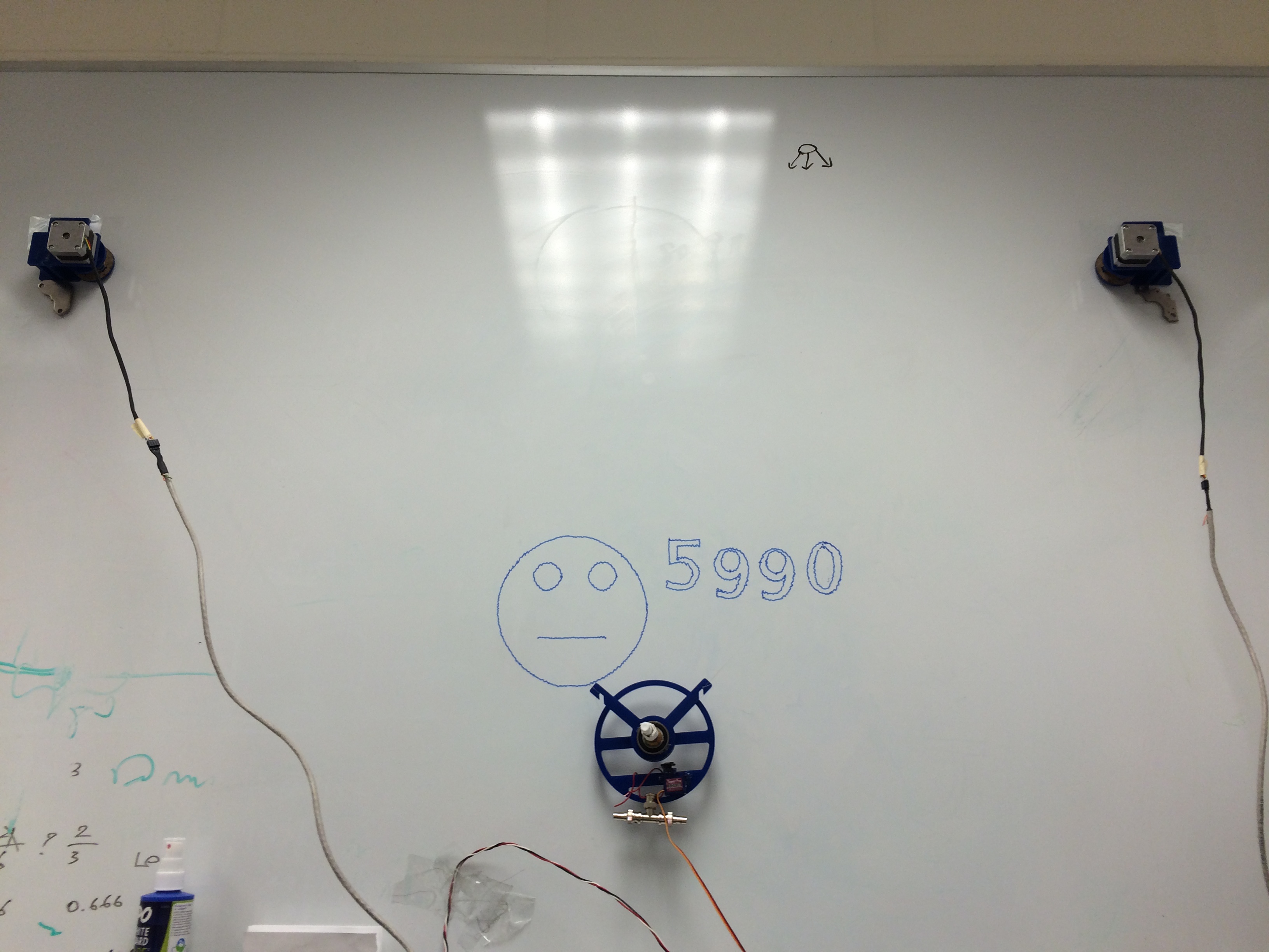
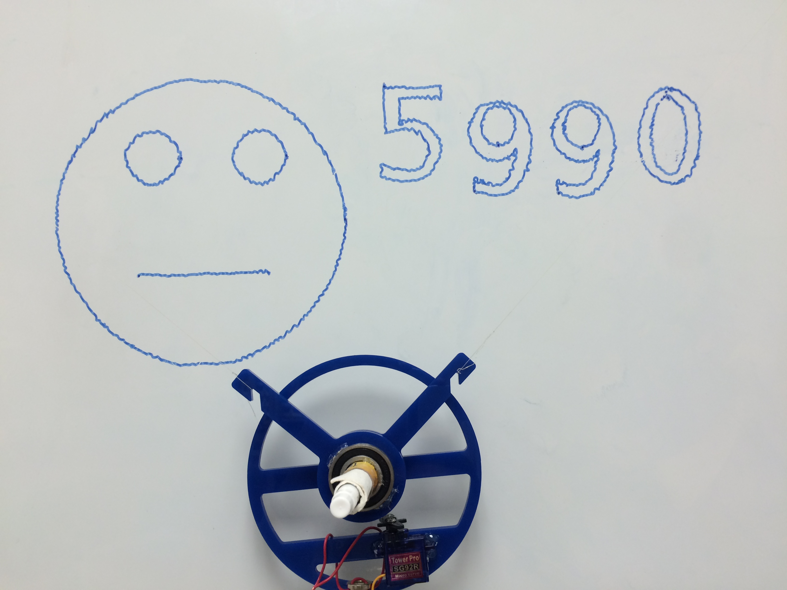
We consider the results to be acceptable and were able to achieve all of our primary goals.
Conclusion
Overall our project was a success. We were able to convert SVG images to G-code, input it into our code and have our plotter draw a decent image. The drawings were not completely smooth, but given our limitations of stepper motors and power supplies, we were able to achieve acceptable results.
Future Work
Given more time, we would like to replace the string with fishing line to improve the drawing quality. We would also like to factor in motor acceleration and deceleration in our algorithm to draw smoother and more rapidly as it is rather slow.
Work Distribution
| Curran | Keshav |
|---|---|
| Designed and implemented interpolation algorithm | Designed and built hardware |
Code Appendix
The complete code is available here.
![]()
![]()
![]()
![]()