Enabling Inter-Integrated Circuit (I2C) communication with RPi.GPIO
Nithya Subramanian (ns796) & Aparna Ramanathan (ar2225)
Final project for ECE 5990 spring 2016 at Cornell University
Objective
The objective of this project was to develop an I2C driver that can be used with RPi.GPIO to set up I2C communication with raspberry pi. RPi.GPIO currently does not support communication modes like I2C, SPI, single-wire interface etc. We have to use solutions like wiringPi for this purpose. We provide a python file which you can download here and plug it in your python code and this works in harmony with RPi.GPIO. There are some other alternative python drivers available for I2C which are listed in section Other Solutions.
How does it work?
One can download and add the python file to their project. Then call the functions in the python file such as simple read/write integer and string transmissions to enable an I2C slave connect to the raspberry Pi master through I2C protocol.
Introduction
I2C is a serial communication protocol that uses two wire interface consisting of SCL (clock) and SDA (data) in open drain configuration. A typical I2C bus is shown in the picture below.
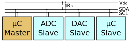
Typical I2C bus.
Each slave has its own unique slave address. The connection is initiated by the i2c master. The default state for the two SCL and SDA lines are high. Each i2c command has a start condition and ends with a stop condition. In both these conditions SCL is in high state, while SDA has a low to high transition for start and high to low for stop. I2C bus can do unlimited 8 bit data transfers and each byte should be followed by an acknowledgement byte. For a detailed explanation on how i2c bus works refer the following link.
In our configuration we used a raspberry pi model 2 B as the master on the i2c bus (raspbian kernel version 4.1.y) and an arduino Pro Trinket (ATMega238P) as the i2c slave.
High Level Design
We used the linux kernel’s SMBus drivers to create an I2C implementation. The other options we evaluated to implement the drivers are:
- Developing register level drivers.
- Use the ioctl() function calls to create drivers in access the SMBus instead of using calls to the existing SMBus drivers.
The raspberry pi 2 model B uses the BCM2836 Broadcom chip. This uses the BSC module (Refer section 3 of the device datasheet) for using the raspberry pi as the I2C master and the SPI/BSC SLAVE module (Refer section 11 of the device datasheet) for using the raspberry pi as slave. Register level I2C drivers for raspberry pi required us to develop drivers for both these modules, one for raspberry pi as master and another for raspberry pi as slave. However, due to time constraints we were unable to pursue this method.
We opted to use the SMBus drivers itself as it had support in python and could be smoothly interfaced with the python code. The advantage of using the SMBus for I2C is that the SMBus command set can then be translated automatically to the I2C adapter.
What is SMBus?
SMBus or System Management Bus protocol is a subset of the I2C protocol. Hence, it is a stricter implementation of I2C. It is possible to use the I2C protocol on using SMBus on many devices as their I2C implementation only supports this subset. The SMBus kernel documentation which can be found here elaborates on the protocol implementation.
Getting started with the SMBus
The python SMBus and the I2C-tools which has the SMBus driver had to be installed on the raspberry pi. Follow the commands in the adafruit reference link listed here for configuring the linux kernel to support i2c.
Clock Frequency
We use the default clock frequency of 100 KHz. The maximum clock frequency of the SMBus is 400 KHz. To change the clock frequency we will have to change the configuration in the /boot/config.txt file on the raspberry pi.
Follow the instructions here to change the SMBus clock frequency.
Software Design
The following section details the software implementation.
i2c_master.py
The following table lists the functions in the i2c_master.py file.
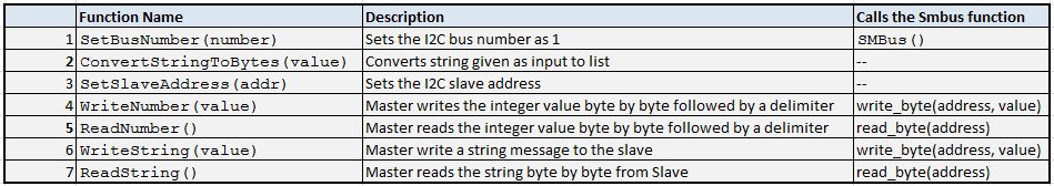
Description for functions in i2c_master.py.
The SetBusNumber() function parses the number for the I2C SMbus to be enabled. By default this is set to 1. That is, I2C-1 is enabled by default.
The SetSlaveAddress() function sets the parsed slave address for a the I2C bus. By default the slave address value is set to 0x04.
ConvertStringToBytes() uses the ord() function in python. This takes the string as input and converts it into a list of ASCII characters. This function is used when transmitting a string.
WriteNumber() function uses the SMBus function write_byte(). This function is straightforward and is a just a wrapper for write_byte(). This is used to write a single byte of data. A delimiter is transmitted to indicate the end of message.
WriteString() function also uses the the SMBus write_byte() function itself. However, the data (which is a string) being sent is converted into a list of ascii values, and then transmitted to the slave byte by byte. It should be noted that a delimiter is also transmitted to indicate the end of message.
ReadString() function also uses the the SMBus read_byte() function itself. However, the data (which is a list of ascii values) being received is converted to a string using the python function unichr(). The data is continuously received till the delimiter is reached. Once the delimiter is received, the data reception stops.
A reference for the SMBus source code is provided here to change the SMBus clock frequency.
Test Application
The i2c_master_test.py is the program used to test the driver on the master (raspberry pi). Similarly another arduino code i2c_slave_datatest.c and i2c_slave_ledtest.c were developed for the Pro Trinket kit. The following sections elaborate on each of these programs.
Test code for I2C master (i2c_master_test.py)
This code is the application for testing the i2c_master.py code. The following pseudo code explains the program flow of the test code.
Pseudo code for i2c_master_test.py
Development with the arduino
We used the arduino Trinket and the Pro Trinket boards for development of the slave module. The boards use the pre-flashed software bootloader to program the devices on them. We used arduino development IDE to program the software. It should be noted that it is essential to add the board support for the arduino trinket and the pro trinket boards in the arduino IDE. The link here shows how to add the support.
One of the arduino trinkets we used could not flash the program. The issue turned out to be because of a corrupted bootloader. Also the arduino trinket board has issues using the Wire drivers of the arduino we chose to stick with the Pro Trinket kit for the testing I2C. In the final testing we used the Pro Trinket as the I2C slave with the software developed using arduino IDE.
In the final testing we used the Pro Trinket as the I2C slave with the software developed using arduino IDE.
Test code for I2C slave (i2c_slave_datatest.c)
This is an application on the Pro Trinket to test the i2c read and write for sending bytes and strings. The explanation for the functions used is elaborated in the pseudo code for i2c_slave_ledtest.c
Test code for I2C slave (i2c_slave_ledtest.c)
This code is an application on the slave device (ATMega238P) to test the functionality of the i2c driver on the raspberry pi. When using this application with i2c_master_test.py, the user is allowed to control the state of the GPIO pin connected to the led. Following is the pseudo code for the program.
Pseudo code for i2c_master_ledtest.c
Hardware Setup
I2C Master was raspberry pi 2 model B which operates at 3.3 Volts though it can withstand up to 5 Volts. I2C Slave used in our testing was a Pro Trinket kit (ATMega328P). The operating voltage is 5 Volts for ATMega328P.
Ideally a bidirectional level shifter has to be used in such I2C connections. However, when using the 5 Volt device as slave and the 3.3 Volt device as master, the communication happens without any issues.
Following diagram shows the I2C connections for raspberry pi 2 model B and Pro Trinket
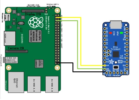
I2C connections between RPi 2 Model B and Pro Trinket.
Results
In a nutshell, it is a master-slave system allowing more than one master to connect to several devices on the bus. The devices can communicate at the rate of 100KHZ to 400KHZ. It is highly preferred over the other communication protocols such as SPI and UART because of the possible elimination of device contention on the SM bus, the extension to connect more than one master to the slave devices and the allowable frequency range for the device clock synchronisation etc. I2C however has an overhead in data interchange. For every 8 bits of data interchange, there is one extra meta-bit data that needs to be transmitted (ACK/NACK).
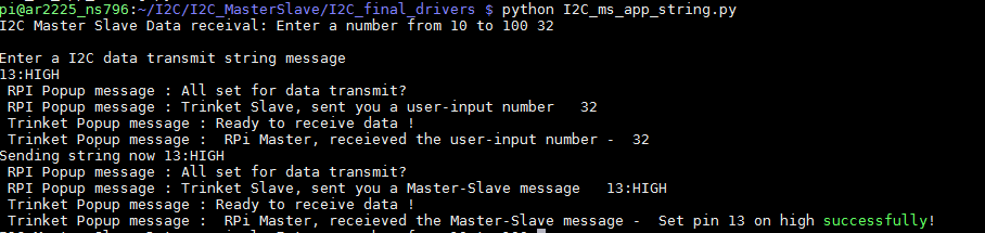
Our application tests the simple data transmission (Integer and string data) using I2C protocol using RPi master and Trinket slave. A test application to monitor the Trinket-LED glow on data transmission between master-slave using I2C serves as a working demo to test the I2C functionality. Here, the user input message from the master is parsed and interpreted as a command to set Trinket LED glow HIGH/LOW by the slave. In addition the succesful transmission of the message is validated as a console-output 'SUCCESS' message at the master end. The following section covers the test results and various 'SUCCESS'/'FAILURE' case outcomes for the I2C application.
Application Nuances:
If a user-input value of a string message is
13 : HIGH
then the application sets the pinMode 13 as the Trinket output pin and the output is set HIGH on I2C data transmission
If a user-input value of a string message is
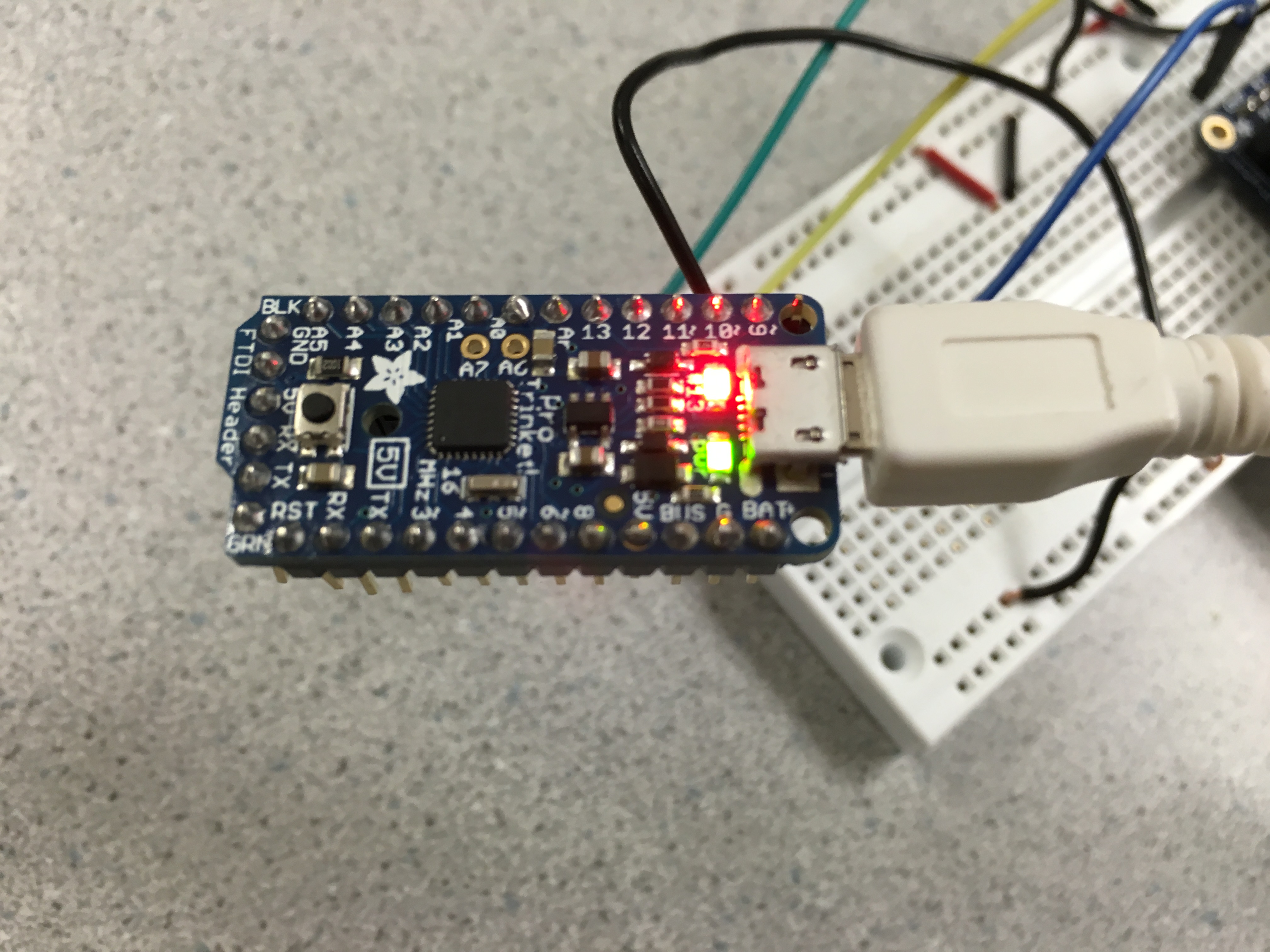
13 : LOW
then the application sets the pinMode 13 as the Trinket output pin and the output is set LOW on I2C data transmission
If the user input message is
13 :
then the application sets the pinMode 13 as the Trinket output pin and does not execute any command when LOW and drives it LOW when set HIGH by default
The output transmission 'SUCCESS'/'FAILURE' messages are displayed on the console for successful I2C data transmission in RPi-Trinket master-slave setup at the user-interface of the application
This section lists the screen-shots, pictures and videos of the output obtained in the demonstration.
Output of i2c_slave_datatest.c
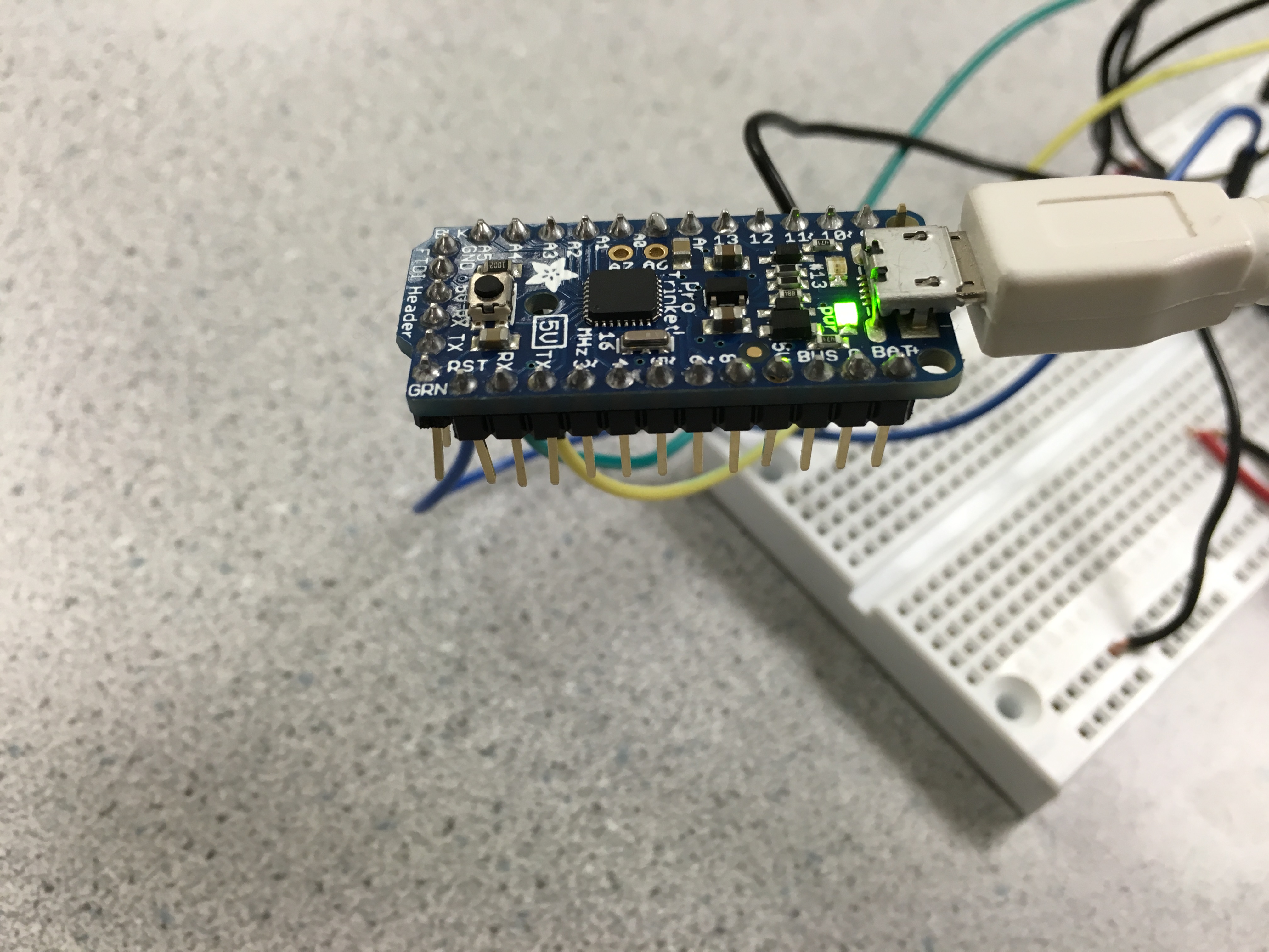
Output screen-shot of i2c_slave_ledtest.c - Set LED high
Output picture of i2c_slave_ledtest.c - Set LED high
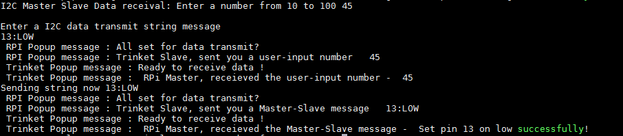
Output screen-shot of i2c_slave_ledtest.c - Set LED low
Output picture of i2c_slave_ledtest.c - Set LED low
Working Demo
Conclusions
We were successfully able to implement an i2c python driver that uses the SMBus functions which can be used in conjunction with RPi.GPIO. This can be tested by any user who follows through the step by step approach mentioned in the report.
We were unable to implement the register level drivers as it required more expertise and time. We also investigated and tried to implement the i2c drivers with RPi.GPIO as a single package. However, that task has not been completed. This is another area where future work can be done on this project.
During our research we also found that with the new SMBus implementation, it is possible to use raspberry pi as a Slave with another raspberry pi as the master. This topic would be a good starting point for future development of the project.
Appendix
Commented Code
Our code can be downloaded as a zip file here.
I2C_RPI_TRINKET_SOURCECODEOther Solutions
WiringPi pigpio Onion-I2C.pyReferences
Data Sheets
BCM2835 Datasheet ATMega238P Datasheet Pro Trinket getting started Trinket getting startedKernel Documentation
Kernel I2CVendor Sites
Arduino Raspberry Pi SparkfunCode/Designs referred to
BCM2836 register level drivers BCM2835 I2C slave register level drivers rpi-4.4.y source code i2c-toolsAcknowledgements
We would like to thank Prof.Joseph Skovira and the teaching staff for their support, guidance and encouragement throughout the project. We would also like to thank the teaching staff Gautham Ponnu for sharing this html format with us.