Oyster Harvester
Rohit Jha, Caleb Zhu
Objective
The oyster harvesting process is laborious and tedious, requiring immense patience and substantial man hours. Our project attempts to minimize the intensive man hours by automating the navigation and unclipping of oyster cages with a robotic boat controlled by a Raspberry Pi. The conception for this project came from Widow's Hole Oysters, based in Greenport, New York.
Introduction
To simplify the process of creating an autonomous water traversing vehicle, we decided to split the project into three parts:
The design of the boat is crucial for creating a craft that is buoyant and balanced enough to support all the necessary hardware needed for navigation without fear of tipping over and damaging expensive equipment.
The navigation algorithm to be developed is the bread and butter of the project. We decided to use openCV with a PiCam as the base for the navigation due to its large user base. Subsequently, the implementation of navigation would be broken down into object detection and a navigation algorithm.
The unclasping mechanism is meant to model the detaching of oyster cages from their lines, so that they may be freely reeled in to shore by our craft or some other pulley system. This was a low priority task as we found that implementing navigation proved to be more time consuming than we initially thought. Therefore, the unclasping mechanism would be tackled after navigation had been completed.
Boat Design
We wished to mitigate the total cost for this project, as we were limited to having a total of 100 dollars for our budget. We could have chosen to purchase a remote controlled toy boat that would have permitted us to place more emphasis on the navigation algorithm and the unclasping mechanism. However, we shifted away from this idea as we believed the toy boat would not have enough spatial capacity for the Pi, the TFT, a protoboard, and a power supply. This limitation required us to manually construct a rudimentary prototype that would float in water without frying electrical components.
The first task item was determining a boat base that would be cost effective while floating with non-evenly distributed weight. One option that we eventually chose was using low density foam, as the density of the polymer itself is similar to water. A large amount of the volume in foam is air, making it a conducive for a floatation device. We therefore cut up a square portion of styrofoam that would be large enough to hold all of our various components, along with a square plastic sheet taped onto the styrofoam.
Custom water-wheels were designed using Autodesk Inventor and printed through Cornell’s Rapid Prototyping Lab. The wheels were designed to be fixtured using M3 screws to the servo’s provided attachment. An image of the CAD rendering is shown below in figure 1.

Figure 1: CAD wheel design
For most robot designs, there need only be two wheels for longitudinal and latitudinal movement, with a clockwise and counterclockwise moments being used to pivot/turn the system. We were concerned with this design, as we feared that any sharp pivot would cause the camera’s frame to overshift, resulting in our robot to constantly spin in place. Therefore, we chose to include four wheels, 2 for lateral movement, and 2 for longitudinal movement.
The final crucial component for our boat design was the placement of all our electrical components. We chose to have a red platform that could sustain all our items while permitting us to put velcro on the surface without damaging the overall structure (styrofoam would have been heavily damaged if this was the case). To maintain our buoyancy, we needed close to equal weight distribution to avoid tipping. We accomplished this by mounting a picamera to the front of our boat structure, with the camera being further mounted and supported by the Raspberry Pi and the TFT screen on its backside. On top of the TFT screen, we placed a protoboard that would control our four servos for navigation. Adjacent to the protoboard, the TFT screen, and the Pi, we had a mini breadboard whose purpose was to mimic the GPIO pins located on the Raspberry Pi. To power the whole system, we attached a 6 Volt battery pack to the back of the boat to power the servos and attached a power bank used to power the Raspberry Pi. A picture showing our boat is shown below in figure 2.
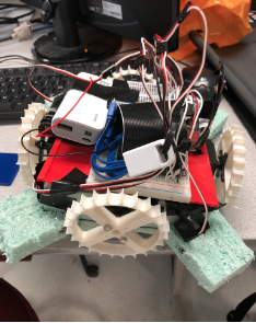
Figure 2: Final Boat Design
Servo Control
Movement of the boat was a crucial part in developing a robust navigation algorithm. After calibrating our servos, we used the framework of servo control from a previous lab, we modified the implementation to include two additional servos. After already having implementation for two servos, implementing four required only simple hardware and software changes. A basic wiring schematic of our boat is shown below (Figure 3), not including the PiTFT and PiCam which are simply plugged into the RPi.
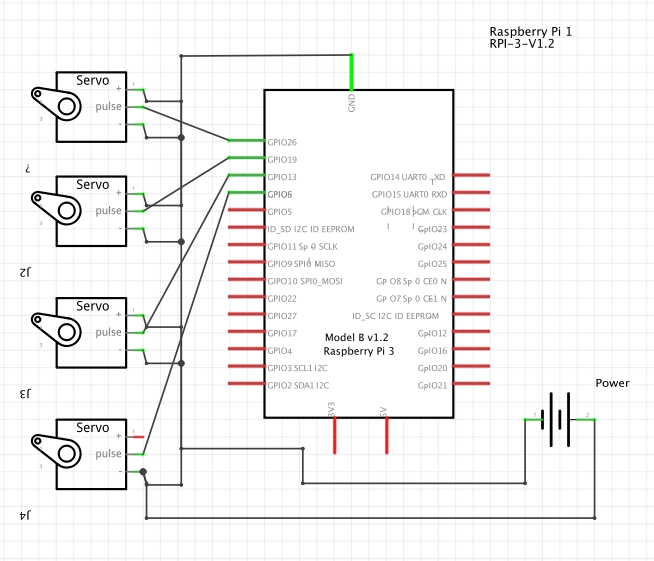
Figure 3: Servo Control Schematic
As evident from the diagram, we used GPIO pins 26, 19, 13, and 6 to control our servos. We deliberately chose these pins as their location made it easier for wiring the servos input signal into the GPIO pin. Table 1 briefly summarizes the corresponding pin servo relationship.
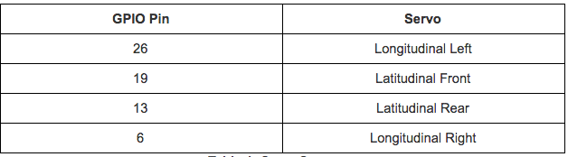
Table 1: GPIO Pin/Servo Relation
Changing direction with this model was noticeably easier in comparison to a robot we created earlier. To move forward, we had the longitudinal left servo spin in a clockwise motion while the longitudinal right servo spun in a counterclockwise motion. A similar logic was followed for latitudinal servo directional manipulation.
Navigation
One technique we viewed as a potential solution to navigation was motion detection. We initially believed that in open water, the PiCam would be able to draw a bounding box over any object that moved. However, we realized that this idea would not be successful because there was no easy solution for object distinguishability. After some thought, we discovered another manner to simplify the navigation process: shape detection.
In order to implement navigation, we started with first getting our system to identify shapes that would be used to model our oyster farm. A triangle marked the beginning post, squares marked cages, and a pentagon modeled the end post. Conceptually, this was very easy to understand; conversely, it was difficult to implement, with the chief reason being the PiCamera’s video capture ability.
The camera itself does a decent job in terms of recognizing black objects from lighter color objects, making object detection easier. We had some issues with color detection, as we did not realize the built-in contouring contoured based on white borders. Our binary thresholding from gray-scale to black and white was inverted and therefore the objects we wanted to focus on were black while the background was white. After realizing our mistake, we inverted the threshold which made the background black while objects were white and this remedied the issue. An example of a sample output of shape detection is shown in figure 4, where the number of sides and area of the contour are displayed.

Figure 4: Shape detection of Triangle and Square
With a functional shape detection algorithm, we began to differentiating the significance of each shape for robotic movement. Figure 5 shows a transition diagram highlighting the logic of our code structure.
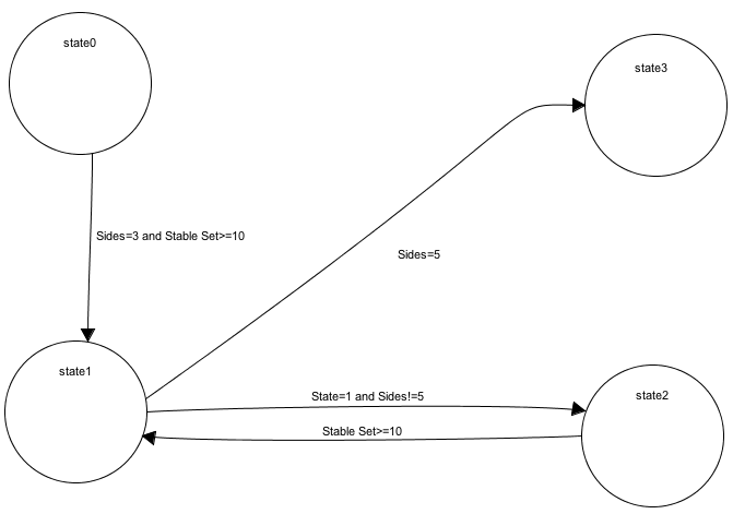
Figure 5: State Machine
State 0 represented the vessel navigating to triangle for correct object detection. Because our TFT was covered up, it was not readily apparent as to when the triangle was fully detected. We had the robot shift its position until the camera had centered the the triangle axis. If it had not recognized the center of the access, the TFT screen displayed “triangle in range”. To validate the robot correctly recognizing the shapes, we created a variable called stable_set. This variable served as a counter in order for the robot to progress to the next shape. If the robot failed to reach a stable_set count less than ten, the count would cycle back to zero, otherwise the robot would move to State 1.
State 1 was the state where the robot actively searched for a square. As delineated earlier, a square will represent an oyster cage that will need unclasping. State 1 can progress to two possible states: state 2 or state 3. State 2 represents the square’s x-axis being in range and centered, while state 3 represents a pentagon shape. Once again, in order for the robot to transition to the next state (predicated on number of determined sides), the robot needs to have the image centered for 10 stable sets. Once the robot reaches state 3 and has looped through ten stable sets, all the servos stop and the robot is suspended in the water.
Results
After testing our implementation out of the water by manually moving a board with corresponding shapes in front of the camera, we configured the RPi to launch our script on startup by modifying the RTC local file. The RPi was then launched and placed into a tub of water with shapes pasted onto the wall. Due to our out of water testing, the robot worked fairly well during initial in-water testing. Slight modifications were necessary to tweak tolerances for smoother operation, but we were largely satisfied with the operation after a few test runs. Full operation can be seen in our demo recording.
Conclusion
We delivered a prototype for an oyster harvester that successfully makes a distinction by shapes. We learned that shape detection is more difficult in terms of implementing/debugging compared to color detection. In open water, we believe that colors can be easily easily washed out due to water damage. Additionally, we realized that buoyancy calculations are crucial for the success of any aquatic project. We hope that future teams will continue this project and add onto the implementation laid out by us in this project.
Future Work
Unfortunately, we did not complete the full scope of project we had set out with. Due to unforeseen complications getting navigation to work as well as making our craft reliable and safe in the water, we were unable to focus much time on the unclasping mechanism. We had a few ideas modeled out, and given more time, we would focus on getting this mechanism to work. The main idea was to use two small DC motors with attached threaded rods to create linear motion out of the rotational motion of the threaded rod with a small attachment. This attachment would have a threaded hole to seat the threaded rod, and two more holes for a hook and a guide rod. To control these DC motors, we would have had to create an H-bridge using NFETS and flyback diodes.
We additionally had created a rough schematic of what the intended design for our H-Bridge, which is shown in figure 6.
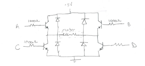
Figure 6: H-Bridge
The first DC motor would unclasp the carabiner by pulling in its latch with the attached hook, and the second DC motor would pull down on the rope the carabiner was attached to, allowing the boat to move backwards and free the carabiner from the rope and create an untethered cage. The figure below (figure 7) shows one of the DC motors with the hook attachment which was 3D printed. We recommend teams in the future to machine this attachment out of light aluminum, as the plastic used in 3D printing creates a lot of friction in the threads and prevents smooth operation.
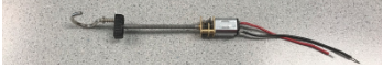
Figure 7: Unclasping Mechanism
Additionally, the boat design could be improved as well. By doing some buoyancy calculations as well as some mass modeling, a proper craft could be printed with onboard mounting for servos as well as electrical components. This would make the craft much more sturdy and waterproof, and allow for neater packaging and smoother operation.
Work Distribution
Initial work was divided into hardware and software. Caleb tackled boat construction and wheel design, while Rohit worked on installing openCV and implementing object detection. As the project began to come together, work was done together to create a navigation algorithm as well as package components into its final form. Troubleshooting was a team effort with much help from Professor Skovira, the TAs, and other students in the class.
Code Appendix
/* * gray_vid_2.py: * * ECE 5725 * Rohit Jha, Caleb Zhu * Oyster Harvester import numpy as np import cv2 import time import imutils import RPi.GPIO as GPIO import sys GPIO.setwarnings(False) GPIO.setmode(GPIO.BCM) GPIO.setup(26,GPIO.OUT)#Set GPIO pins for servos GPIO.setup(19,GPIO.OUT) GPIO.setup(13,GPIO.OUT) GPIO.setup(6,GPIO.OUT) #bailout button GPIO.setup(27,GPIO.IN,pull_up_down=GPIO.PUD_UP) def GPIO27_callback(channel): GPIO.cleanup() cv2.destroyAllWindows() sys.exit() GPIO.add_event_detect(27,GPIO.FALLING,callback=GPIO27_callback,bouncetime=300) #initializing GPIO outputs for servos. latF = Lateral Front, longL = Longitudinal Left, etc. latF = GPIO.PWM(19,46.511)#default values for servo latR = GPIO.PWM(6,46.511) longL = GPIO.PWM(26,46.511) longR = GPIO.PWM(13,46.511) latF.start(0) latR.start(0) longL.start(0) longR.start(0) #functions to simplify motion calls later on def pause_motion(): latF.ChangeDutyCycle(0) latR.ChangeDutyCycle(0) longL.ChangeDutyCycle(0) longR.ChangeDutyCycle(0) def shuffle_forwards(): longL.ChangeDutyCycle(7.834) longL.ChangeFrequency(46.083) longR.ChangeDutyCycle(6.103) longR.ChangeFrequency(46.948) def shuffle_back(): longL.ChangeDutyCycle(6.103) longL.ChangeFrequency(46.948) longR.ChangeDutyCycle(7.8341) longR.ChangeFrequency(46.083) def shuffle_left(): latF.ChangeDutyCycle(6.103) latF.ChangeFrequency(46.083) latR.ChangeDutyCycle(7.8341) latR.ChangeFrequency(46.083) def shuffle_right(): latF.ChangeDutyCycle(7.834) latF.ChangeFrequency(46.083) latR.ChangeDutyCycle(6.103) latR.ChangeFrequency(46.948) #class that receives an input contour and approximates the shape class ShapeDetector: def __init__(self): pass def detect(self, c): shape = "unidentified" peri = cv2.arcLength(c, True) approx = cv2.approxPolyDP(c, 0.04 * peri, True) if len(approx) == 3: shape = "triangle" elif len(approx) == 4: shape = "square" elif len(approx) == 5: shape == "pentagon" else: shape = "circle" return len(approx) cap = cv2.VideoCapture(0) time.sleep(0.1) cap.set(3,640) #setting capture resolutions cap.set(4,480) xCenter = 320 yCenter = 240 x_diff = 0 x_tol = 20 #horizontal tolerance for center of shape vs. center of screen desired_tri_area = 20000 tri_area_tol = 5000 #tolernace for area of shape vs. desired area of shape cnt_area_diff = 0 x_set = 0 #marks when x axis is within tolerance range area_set = 0 #marks when area is within tolerance range stable_set = 0 #counter used to reduce noise and make sure state is stable before advancing break_bit = 0 #used to exit program counter = 0 #timer variable to prevent stalling during motion state = 0 #state 0 = navigating to triange #state 1 = navigating to next square #state 2 = centering square #state 3 = Reached end at pentagon while(True): start_time = time.time() ret, frame = cap.read() #proceed only if an image is successfully retrieved from the capture call if ret: #gray, blur, and threshold image to more accurately approximate contours gray = cv2.cvtColor(frame, cv2.COLOR_BGR2GRAY) blurred = cv2.GaussianBlur(gray, (5, 5), 0) thresh = cv2.threshold(blurred, 60, 255, cv2.THRESH_BINARY_INV)[1] cnts = cv2.findContours(thresh.copy(), cv2.RETR_EXTERNAL, cv2.CHAIN_APPROX_NONE) cnts = cnts[0] if imutils.is_cv2() else cnts[1] sd = ShapeDetector() for c in cnts: M = cv2.moments(c) area = cv2.contourArea(c) sides = sd.detect(c) #avoids divide by zero errors and ignores small contours if ((M["m00"] != 0) & (area > 2000)): cX = int(M["m10"] / M["m00"]) cY = int(M["m01"] / M["m00"]) x_diff = xCenter - cX #counter used to create discrete movements followed by a pause #to improve diagnosing and prevent runaway motions if(counter < 25): #State 0. If a triangle is in sight, move towards it until #it is centered and an adequate distance away if ((sides == 3) & (state == 0)): cnt_area_diff = area - desired_tri_area if(area_set & x_set): print("in here 1") stable_set = stable_set + 1 if (stable_set >= 10): state = 1 stable_set = 0 counter = 25 if (abs(x_diff) <= x_tol): print("triangle x-axis in range") x_set = 1 elif (x_diff > 0): x_set = 0 stable_set = 0 shuffle_left() else: x_set = 0 stable_set = 0 shuffle_right() if (abs(cnt_area_diff) <= tri_area_tol): area_set = 1 #else: #area_set = 0 #stable_set = 0 #shuffle_forwards() #State 2. Square has been locked onto and now being centered if (state == 2): if (abs(x_diff) <= x_tol): stable_set = stable_set + 1 if (stable_set >= 10): print("square x-axis in range") counter = 25 state = 1 stable_set = 0 elif (x_diff > 0): shuffle_left() else: shuffle_right() #State 1. Searching for next square or pentagon. if ((state == 1) & (sides !=5)): #If square in sight, lock on and center onto square. if ((sides == 4) & (cX > 400)): print ("in here 2") stable_set = stable_set + 1 if(stable_set >=10): state = 2 stable_set = 0 else: shuffle_right() #State 1. If pentagon in sight during state 1, move to state 3. if ((sides == 5) & (state == 1)): stable_set = stable_set + 1 if(stable_set >= 10): state = 3 stable_set = 0 #State 3. Locked onto pentagon and now being centered. if(state ==3): if (abs(x_diff) <= x_tol): print("pentagon x-axis in range") pause_motion() longL.stop() longR.stop() latF.stop() latR.stop() break_bit = 1 break elif (x_diff > 0): shuffle_left() else: shuffle_right() counter = counter + 1 #Advance counter while paused to create breaks between motions elif(counter < 50): pause_motion() counter = counter+1 #When counter reaches 50, reset cycle and begin scanning environment again else: counter = 0 #Print statements to track state of navigation parameters. print("state " + str(state)) print("sides " + str(sides)) print("stable set " + str(stable_set)) print("counter " + str(counter)) print("x_diff " + str(x_diff)) print("contour area diff " + str(cnt_area_diff)) print("----------------------") #Comment out these calls during embedded operation as no monitor is hooked up to display images #cv2.drawContours(frame, [c], -1, (0, 255, 0), 2) #cv2.putText(frame, str(sides), (cX, cY), cv2.FONT_HERSHEY_SIMPLEX, 0.5, (255, 255, 255), 2) #cv2.putText(frame, str(area), (cX, cY+10), cv2.FONT_HERSHEY_SIMPLEX, 0.5, (255, 255, 255), 2) #cv2.imshow('frame',frame) #cv2.imshow('thresh', thresh) #Ends program through keyboard input or TFT button input if cv2.waitKey(1) & 0xFF == ord('q'): break if (break_bit == 1): break # Releases the capture when program finishes cap.release() #cv2.destroyAllWindows() |
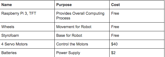
Cost Distribution
Contact
Rohit Jha: rj245@cornell.edu
Caleb Zhu: cz225@cornell.edu
We would like to thank Professor Skovira and all the TA's who have helped us through this nautical journey!