Autonomous Object Tracking Turret
Francis Yu (fy57) and Xitang Zhao (xz522)
May 17th, 2018
Project Objective
For our ECE 5725 Design with Embedded Operating Systems final project, we created an autonomous object tracking turret. Our turret is able to locate blue objects in real time and autonomously track it with two degree freedom of motion (rotation and tilt). Our system can also be remotely controlled to emit a laser beam and to fire a rubber band at the target.
Introduction
Inspired by the surface-to-air missile in the movie Olympus Has Fallen and excited by the influx of the useful applications of computer vision, we wanted to create a project that seamlessly integrates both elements. This fascination led to our creation of the autonomous object tracking turret. At a high level, the mini computer Raspberry Pi serves as the brain of our turret. The Pi processes the images captured by the camera module to detect the target object and then outputs feedback control signals that move the servos to follow the object. Furthermore, when the Pi receives keyboard commands from the keyboard, it can fire a laser beam and/or a rubber band to the target object.
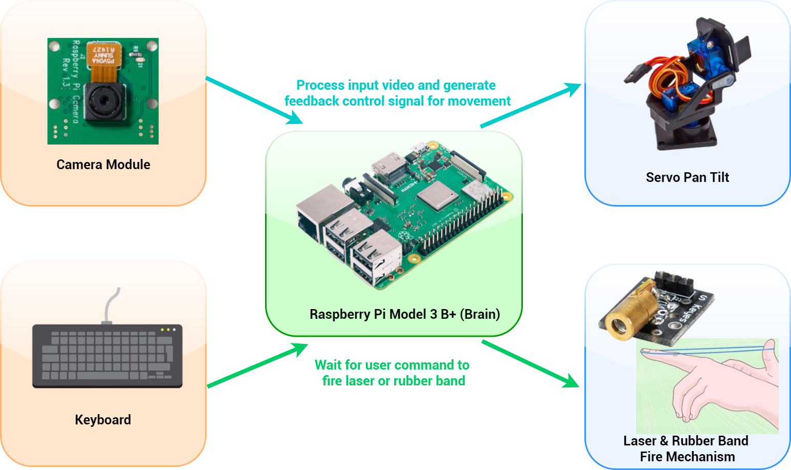
Figure 1: High Level Design
Hardware Design
The hardware design of our turret consists of a Raspberry Pi, a pan tilt kit, a camera module, a laser, and a rubber band projectile mechanism. We first started with building the pan-tilt kit. The pan-tilt kit is nicely packaged kit that allowed us to get the desired motion we wanted for our turret. It consisted of all the screws, plastic housing, and two micro servos (with feedback) that can each move 180 degrees. Once put together, we quickly began to test and control each of the motors, one for rotation, and one for tilt. Interestingly, despite the popularity of these micro servos, we were not able to find a reliable datasheet that specified the operating frequencies of these motors, only the operating periods were provided. Thus, we started testing these servos with the same frequency as the Parallax servo used in class, which was 50 Hz. Surprisingly, the frequency used in our previous servos worked for these servos also. The data sheet specified 1.5ms period on as the center value, 2msec as all the way left, and 1 msec all the way right. Using these values and a 50 Hz period, the duty cycles were calculated to be between 7.5% and 10% for full range of motion (1/50*period). However, when we were actually testing the motors, we determined that these duty cycles, given in the datasheet, gave us less than the 180 degree specified. Therefore, after further experimentation, we determined that the duty cycle range that would give us the exact 180 degree motion is between 3.5% for full right and 13% duty cycle for full left. Due to the limitation of the Pan Tilt kit, in which the tilt motor was limited to only around 130 degrees of motion by the physical plastic; we determined the appropriate duty cycle range of the tilt servo to be from 4% to 11%.
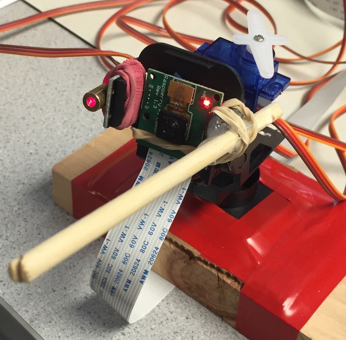
Figure 2: Autonomous Object Tracking Turret
Once we got the pan tilt working with the servos moving to the desired angle, we integrated the servo control with the camera to allow for the autonomous tracking of an object. As seen in the image above, the camera module is directly attached to the pan kit such that both the rotation and tilt movements move the direction the camera is pointing at, giving us the ability to view the full half of the room. We decided to use rubber bands to secure to camera because not only were rubber bands strong enough to hold the camera in place, but it also allowed for minor adjustments when needed. In addition to the camera, we also mounted a laser pointer on one side of the turret that has a control line which allowed the laser to be controlled via software; though, the range of the laser was a mere 5 feet. Another added feature of our turret, which was a distinguishing feature for our project, was a DIY rubber band shooting mechanism. To weaponize our turret, we hot glued a ,third, continuous rotation servo on the back of the turret as well as a grated chopstick on one side of the turret to serve as our weapon. On command, the servo would rotate, allowing the rubberband to be shot at the desired rotation and tilt angle. The continuous parallax servo used to operate the firing mechanism operated at 1000 Hz with 1.5% duty cycle as full clockwise rotation.
Software Design
The software design of our system is divided into three main portion: object recognition algorithm, PID control algorithm and multi processing algorithm.
Object Recognition Algorithm
Our object recognition algorithm detects the largest blue object viewed on camera and extracts its center position. This algorithm is made easy with the openCV library. To start, we first installed the openCV library onto our RPi. There are several ways to install openCV. We decided to install openCV directly from RPi Ubuntu’s application repository by entering the following command in the command prompt (sudo apt-get install libopencv-dev python-opencv). Though the application repository openCV is only at version 2.4.9 (the latest version is 3.4), we avoided several hours of installation time and got openCV up and running in several minutes; the 2.4.9 version came equipped with enough functions we would like to use. As for the specific implementation, our object recognition algorithm can be broken down in the following steps.
- cv2.VideoCapture(0) is first used to create a video capture object that would return a 640x480x3 picture array whenever videoCap.read() is called. The picture array is 640x480 because we are using the default image resolution and it has a depth of 3 because it has three colors at RGB(red, green, blue) color space.
- cv2.cvtColor is used to convert the picture array from RGB color space to HSV (hue, saturation, value) color space because it is easier to detect a color at HSV than RGB color space.
- cv2.inRange is used to check pixels in the picture array that is in the blue range and creates a mask. It does so by checking individual pixel and compares it with the range. Before we feed in the mask to the following time intensive steps, we sum the values of the mask to check if it is greater than a certain threshold. If yes, we treat it as a valid blue object detection and move on. But if it is below the threshold, we simply skip the following steps and discard it as noise to avoid unnecessary heavy computation.
- cv2.morphologyEx is called twice to apply the open and close operation on the mask, which is useful to get rid of a lot of background noise, separate connecting objects and solidify an object with its hazy boundaries.
- cv2.findContours is used to extract the boundary of the objects.
- Once we have the boundary of an object, cv2.moments is used to extract the spatial moments that can be used to compute the center position of an object. Since we only track one object at one given time, we loop through all the contours we obtained from cv2.findContours to find the object with the max contour and we only pass the max object to cv2.moments for center extraction.
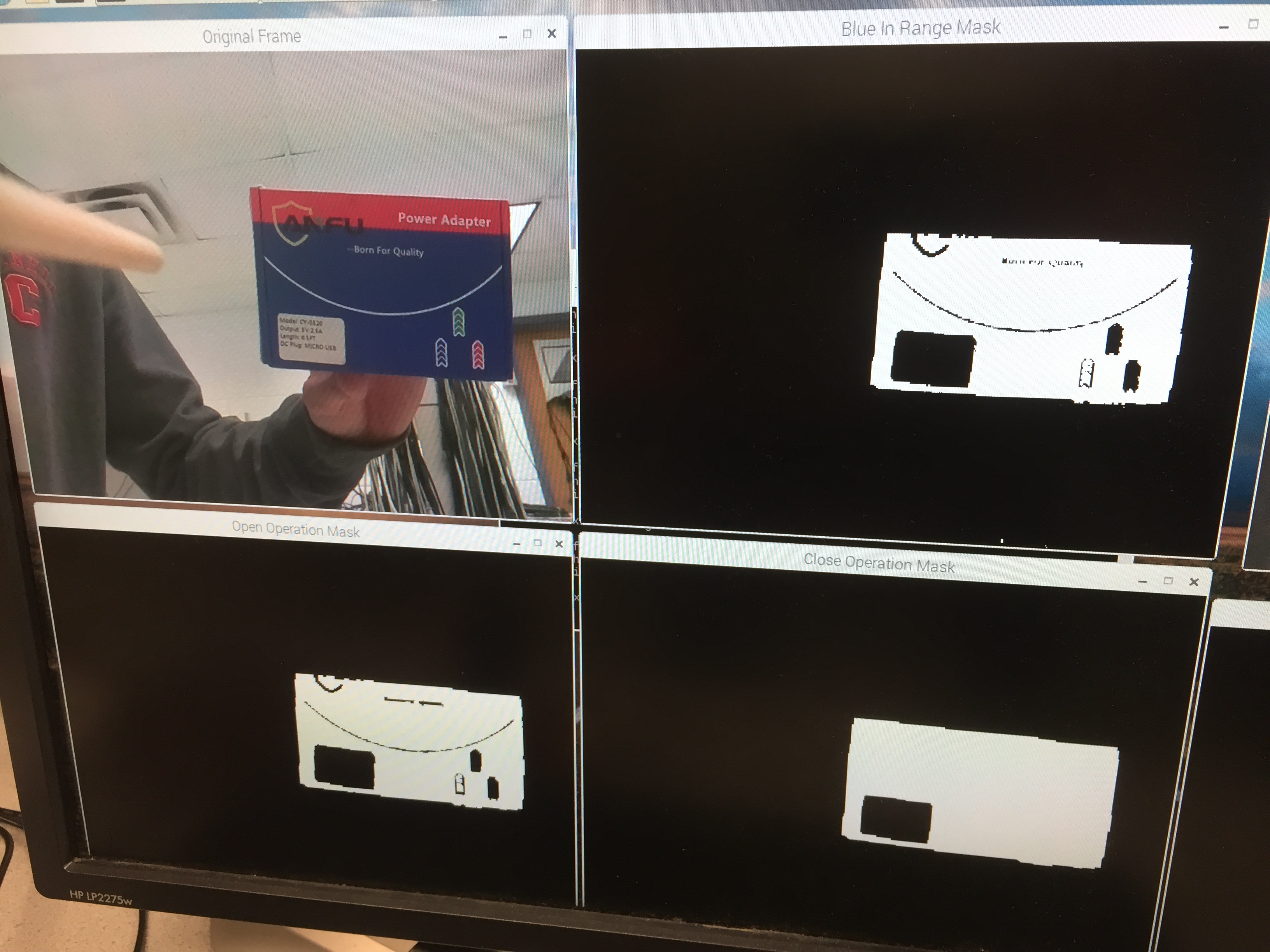
Figure 3: Object Recognition Algorithm: Step 1-Original(Top Left), Step 3-Extract Blue In Range(Top Right), Step 4-Open Operation(Bottom Left), Step 4-Close Operation(Bottom Right)
PID Control Algorithm
The center position of an object extracted from the object recognition algorithm is our target position. We know that our turret’s current position is the center of the camera (320, 240), which is half of the image resolution 640x480. With the target position and current position, we can compute their difference and use it as a feedback to control the servo and make the camera align with the target, thereby achieving tracking. A simple method to implement tracking is to move the camera at a constant slow rate to approach to the target. For example, if the turret detects the object is at the top right corner relative to its current position, it simply moves the servo incrementally to the right and incrementally to the top. With successive small constant movement, the turret would eventually get to the target. However, evident in the description above, this method is not efficient as the servo would move at a constant rate regardless of how close or far the turret is to the target. Thus, to optimize movement, we decided to implement a PID control algorithm that would optimize the motor movement such that the desired target is reached faster.
The PID in a PID controller stands for proportional, integral, and derivative. Each part of the controller plays a role in controlling the motors such that the motors will not only move to the desired location quickly, but also with minimal oscillations. Following some resources recommended by Professor Skovira, we started with simply applying the proportional part of the controller. The proportional part, arguably the most intuitive, simply adjusts the speed/strength of adjustment proportional to the error. In other words, the further away the target is from the center of the frame, the faster the motors will try and adjust. Similarly, the closer the target is to the center, the slower the motors would adjust; we controlled the “strength” or speed of the motor by changing the size of the increment the motor moves at each time step/each loop. While the proportional part of the controller is effective, only having the proportional part caused some oscillation when tracking, thus, again following the same resource outlined below, we continued and incorporated the derivative portion into our system. The derivative portion of the controller allows for the system to tune down the change in velocity such that the system does not overshoot as much each iteration, dampening the oscillations quicker. The basics of the derivative portion are calculated as follows:
- Take the current error (the x -y distance from the center of the frame to the target) and subtract it by the previous error at the last time step
- Divide the result by the time it took between the two captures; that is your derivative term.
Evident in the math, the derivative takes the change in error in account to determine how fast the motor should adjust. If the motors are accelerating to the target, it should be slowed down to eliminate oscillations from the proportional control. Once we added in the derivative portion, our system was able to move and track the target quickly with minimal oscillations and errors, thus forgoing the need for an integral portion. The size of the motor adjustment are modeled with the following equation: Control speed = Kp* proportional + Kd * derivative. The constants Kp and Kd are user decided constants that are system dependent. Further explanation regarding how we chose our constants is further explained in the testing portion below.
Multi Processing Algorithm
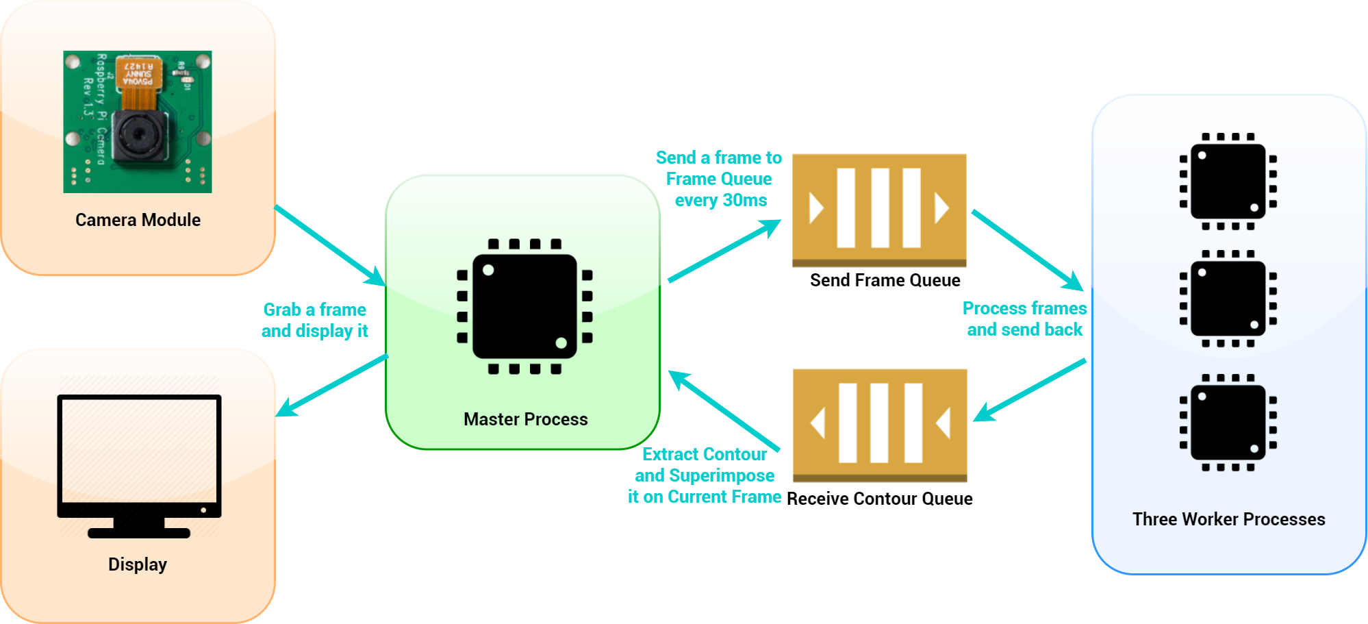
Figure 4: Multi Processing Flow Diagram
The last portion of our software design is the multi processing algorithm. Our object recognition algorithm takes about 120ms to execute, which means it is displaying the video at 8 frames per second. Since a human eye can perceive a noticeable delay in the video when it is below 15 frames per second, there was initially significant delays in our system in terms of both motor control and the display on the screen. To minimize the processing delay and allow videos to display with no perceivable delay, we had to optimize the usage of all four cores on the Raspberry Pi to perform multiprocessing. To do this, with the help of Professor Skovira, we came up with an algorithm in which we assigned one process as the master process and the three processes as worker processes. The master process performed steps 1-3 of the object recognition algorithm stated above: it grabs a frame and checks if the frame has blue object before sending it to a queue in which one of the three worker processes will perform computation intensive open/close operation and contour extraction; the three processes will rotate to grab frames from the queue and can operate in parallel, thus effectively decreases overal computation time. Once processing is done for one frame, the master process will extract the contours sent back from the worker process, display the contours on the screen, and use the contours for PID servo control. This way, the master process grabs and displays the frame independently on the screen, allowing the video streaming from the camera to have no visual delay. Each of the three worker processes can process a frame in 150ms, and since we are processing three frames at the same time now, on average, our processing time becomes around 50ms. The video below shows an example of a frame going through the processing algorithm with one worker process.
The video below shows an example of a frame going through the processing algorithm with three worker processes. Comparing with the video above, we can see that the blue contour is drawn smoother with more worker processes.
Testing, Design Issue, and Discussion
Our turret was built in an incremental design and testing procedure. First, we worked on getting the pan tilt and servo control up and running so we could get our turret to move the range of motion we desired. Initially, we were using the RPi GPIO library to generate software PWM signals to control the servos. We quickly realized that the software created PWM signals were noisy and unstable in a RPi multiprocessor operated environment. The noisy software PWM signals did not control the servos stably and the servos jittered a lot even at their standing still positions. After consulting with Professor Skovira, we decided to change our approach and controlled the servos using hardware PWM with the pigpio library instead. To use the hardware PWM library, we have to first use the “sudo pigpiod” command to launch the pigpio library as a daemon before running our main code. More specifically, we actually entered the command “taskset 0x1 sudo pigpiod” so the daemon was bounded to run at the first core of the RPi. The hardware PWM generated (in pin 12 and 13) were much cleaner PWM signals and significantly reduced the amount of jitter created on the servo. Once we resolved the jitter, we then worked on figuring out the control signals using modular functions that can move the turret to the desired angle.
In parallel with working on the pan tilt kit and servo control, we also worked on object detection with the openCV library. After openCV was installed, we decided to run a sample code we found online to test it, but we received an error from openCV and couldn’t get it to run the sample code. The error says the following: “OpenCV Error: Assertion failed (scn == 3 || scn == 4) in cvtColor, file /build/opencv-U1UwfN/opencv-2.4.9.1+dfsq1/modules/imgproc/src/color.cpp, line 3737”. We initially thought this error is due to the fact that our openCV version was low and we might have to compile and update it to the latest version of openCV. But after a quick run down of google search, we found out that the error can be easily fixed by entering the following to the command line “sudo modprobe bcm2835-v4l2“. This command basically installed the V42l driver or the Video4Linux2 API on the Bcm2835, which was the Broadcom chip used in RPi B+. We also added this command to /etc/modules so it was automatically loaded at boot time. Once we got openCV running, it was smooth to do blue object detection because of the great community support with abundant sample tutorials and the intuitive openCV library that abstracts a lot of details into a single line of function. We were able to extract the center of a blue object in about 10 lines of code. We tested our detection algorithm in different light condition and found that it worked best when the room wasn’t overly bright as brightness caused the camera to re-auto focus. During testing, we discovered and fixed some software bugs in our code, such as a bug that crashes the code when dividing by 0 and a bug that stops object detection due to wrong timing calculations.
Once we had the pan tilt and the object detection working, we then merged the two and used the object detection to output feedback values to control the pan tilt with our PID control algorithm. To tune our PID, we started with setting the integration and derivative terms to be zeros. We settled for a proportional term that responded fast enough and gave a little bit of overshoot, which we found to be 3. We then increased the derivative term until the overshoot oscillation was minimized, which we found to be around 0.005. We didn’t tune the integrational term because the proportional and derivative terms were good enough and our target moved around over time.
Our last step was to add the laser and rubber band fire feature onto our turret. The last step was trivial on the software side. We simply used two gpios: one gpio is toggled whenever the “v” button is pressed to toggle the laser and the other gpio sends out a servo signal that rotates the servo for a second and triggers the rubber band to be fired. On the hardware side, we realized the rubber band fire mechanism we added have some design flaws. For example, the chopstick we used to hold the rubber band was quite long. When our turret looked downward, the chopstick would touch the ground and lift our turret, so we added a wood base to increase the height of our turret to resolve this issue. We also realized in hindsight that we should have mounted the rubber band servo, the servo that controls the rubber band fire mechanism, on top of the tilt servo instead of the left-right rotational servo. We currently mounted the rubber band servo on top of the left-right rotational servo and it can interfere with the movement of the tilt servo when the tilt servo goes too upward. Lastly, we originally planned to load four rubber bands on our turret so it can be fired four times. Later, we realized this wasn’t feasible with our current design because the pan tilt servos we were using couldn’t generate enough torque to hold the pan tilt in place. In fact, it couldn’t even hold two rubber bands, as two rubber bands would generate great enough force to move the tilt servo. We could technically do it but it would come at the expense of losing 1 degree of freedom at the up-down position.
Results
Our autonomous object tracking turret successfully achieved the three core objectives we set forth at the brainstorming stage of our final project:
- Our turret can successfully locate the largest blue object on view in real time with around 50ms average processing latency (or operating around 20fps on average). This was achieved through the multiprocessing library and the usage of four processes (one master process and three worker processes). The master process grabs and displays video frames independently and also sends frames to the three worker processes over a queue for them to perform time intensive open/close operation and contour extraction.
- Our turret can successfully extract the blue object’s target position as feedback parameters for our PID control algorithm, which then controlled the pan tilt servos to track the blue object and keep the blue object align with the center of our camera. Our PID control algorithm was tuned to minimize tracking time and maximize the efficiency of tracking an object with minimal oscillations.
- Our turret can successfully be remotely controlled with a keyboard to emit a laser beam and to fire a rubber band at the target.
Future Work
Despite the success of our project, there are many aspects and future works that can be done to further enhance our turret. Despite distributing the image processing using the Multiprocessing library, we still experienced some latency with the object tracking, which lead to slight delays in object tracking. Since we still could not guarantee that each core was designated to process each frame with the Multiprocessing library. Further research and experimentation can be done, either continuing the use of the Multiprocessing or using FIFO’s, to truly allow our program to be operating in parallel, which will give a 3x speedup. Nevertheless, another issue we ran into was the lack of torque on the servo when the rubberband was attached. The turret’s downward tilt movement was limited by the rubber band when it was loaded due to the pull strength of the rubberband. An easy fix would simply be incorporating more powerful servos with feedback. Another more robust solution is to find a way to also attach the firing motor on the tilt side of the pan tilt kit. In this method, no extra stress on the motors or rubber band would be added when the servos moved, thus allowing the servo’s in both direction to move freely. Obviously, more advanced weaponry can be added to our project, but maybe we’ll leave that to Lockheed Martin. Lastly, another area of improvement is the image processing portion. Despite our successes in extracting a blue object in the frame, more complicated and robust object detection can be developed to further enhance our targeting abilities. Instead of simply shooting a blue object, we can develop facial recognition and tracking software to track down and fire at Professor Skovira.
Conclusion
Overall, our final project was a huge success. With five weeks of time, we were able to brainstorm, design, and successfully create a mini version of a surface-to-air missile that was able to locate and take down, with a rubber band, a blue object in real time autonomously. Through working on this project, we not only applied many skills we have learned in previous labs and in lecture, but we also gained numerous insights from the difficulties we faced throughout. From the lack of torque in the servos, the need to distribute image processing tasks amongst the different cores, and implementing a PID controller, we have learned invaluable skills that include not letting the operating system decide what to do and how to do it, especially in real time systems. We hope this project will serve as a good baseline for any future groups looking to develop an autonomous computer vision system featuring complicated hardware. Both Xitang and Francis feel extremely accomplished and hope to have this project featured on Hackaday and/or other publications.
Team
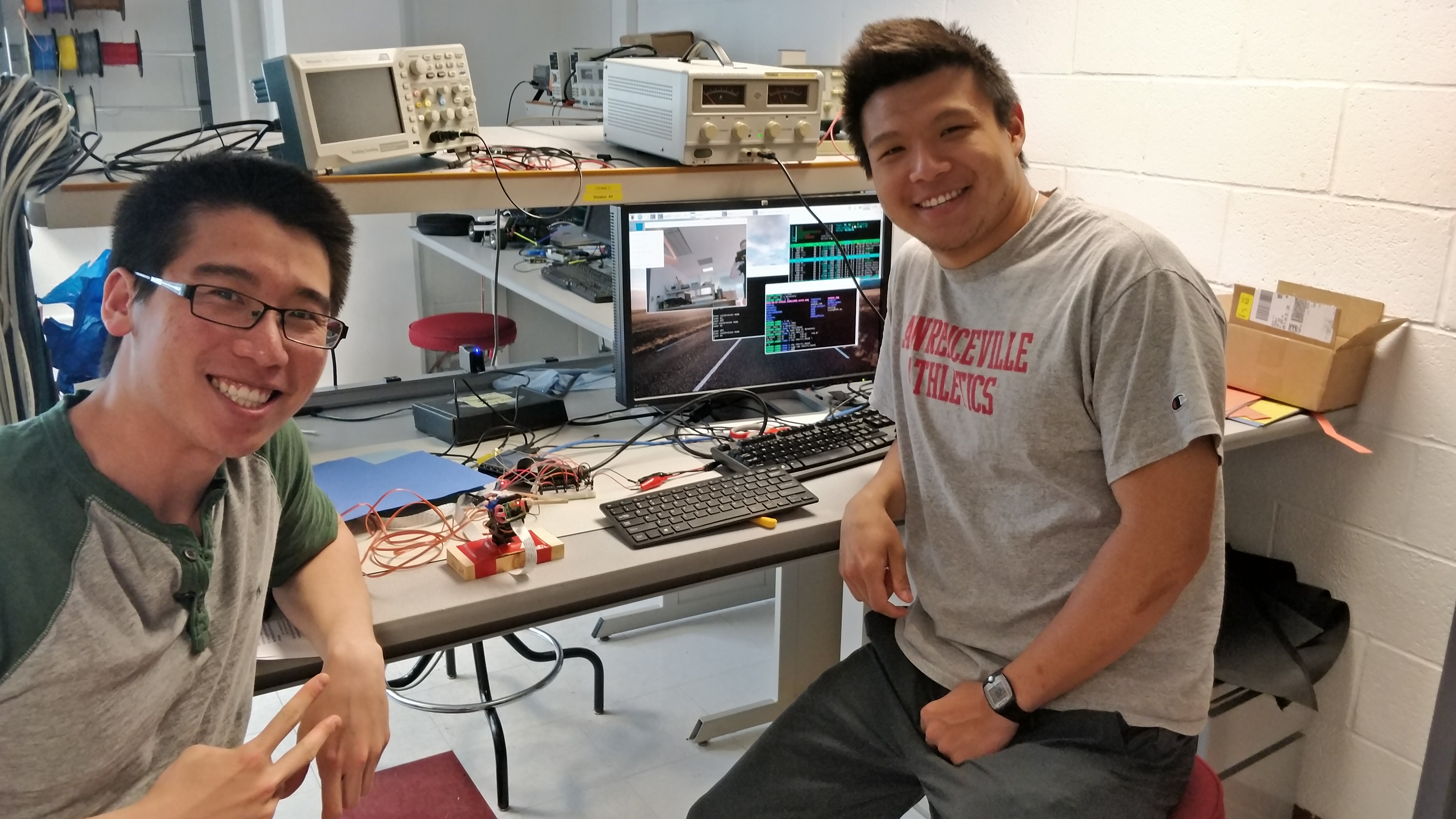
Figure 5: The Dream Team - Xitang and Francis
Francis Yu graduated from Cornell University in 2018 with a degree in Electrical and Computer Engineering and a minor in Computer Science. He is currently pursuing a MEng in Systems Engineering while also partaking Nielsen’s Emerging Leaders Program.
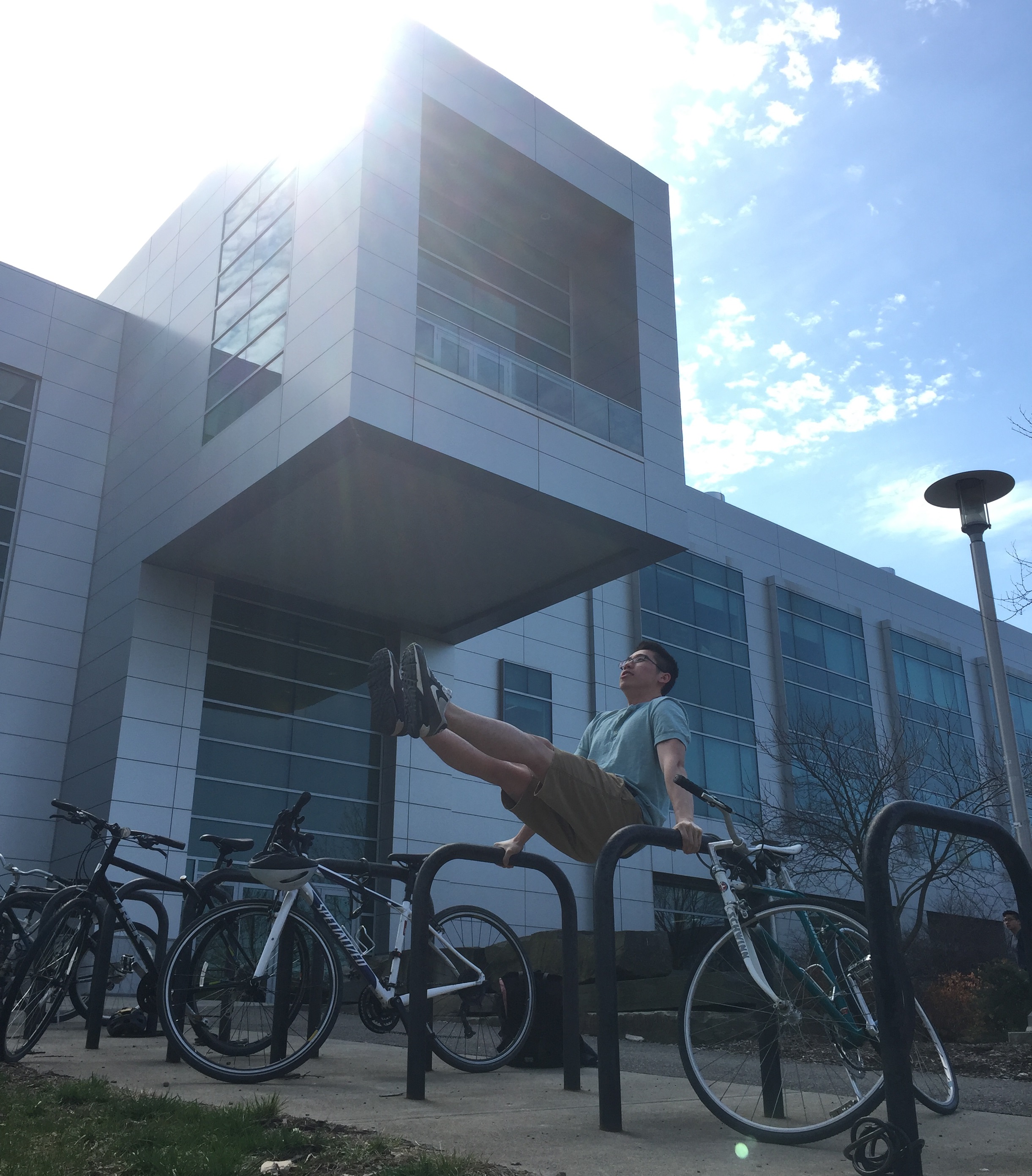
Xitang enjoys spending time in the park, hanging out with kids, teens and elders in local park communities. Doing, chatting, and teaching street workout :D
Appendix
Bill of Materials
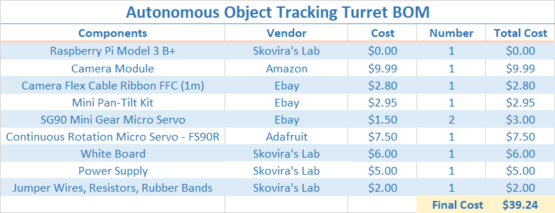
Figure 6: Autonomous Object Tracking Turret BOM
References
- OpenCV Changing Colorspaces: Link
- OpenCV Error Fix: Link
- OpenCV Python Documentation: Link
- OpenCV - Getting Started with Videos: Link
- OpenCV Object Tracking by Colour Detection in Python: Link
- OpenCV Contours: Getting Started: Link
- Python multiprocessing: Link
- Mini Pan-Tilt Kit Assembly: Link
- Continuous Rotation Micro Servo - FS90R: Link
- SG90 Micro Servo: Link
- Website Template Base: Link
Acknowledgement
We would like to thank Professor Joe Skovira and all the TAs, who are always available to help us out in lab and provide guidance and support throughout the semester. It is been a fun ride :D
Work Distribution
- We pretty much work on most of the things together
- Francis: Pan Tilt, Servo Control Algo, Hardware PWM, Laser, Rubber Band, PID Algo, Website
- Xitang: Hardware, Color Detection Algo, Multiprocessing Algo, Website, Website Diagram
Commented Code :
1 2 3 4 5 6 7 8 9 10 11 12 13 14 15 16 17 18 19 20 21 22 23 24 25 26 27 28 29 30 31 32 33 34 35 36 37 38 39 40 41 42 43 44 45 46 47 48 49 50 51 52 53 54 55 56 57 58 59 60 61 62 63 64 65 66 67 68 69 70 71 72 73 74 75 76 77 78 79 80 81 82 83 84 85 86 87 88 89 90 91 92 93 94 95 96 97 98 99 100 101 102 103 104 105 106 107 108 109 110 111 112 113 114 115 116 117 118 119 120 121 122 123 124 125 126 127 128 129 130 131 132 133 134 135 136 137 138 139 140 141 142 143 144 145 146 147 148 149 150 151 152 153 154 155 156 157 158 159 160 161 162 163 164 165 166 167 168 169 170 171 172 173 174 175 176 177 178 179 180 181 182 183 184 185 186 187 188 189 190 191 192 193 194 195 196 197 198 199 200 201 202 203 204 205 206 207 208 209 210 211 212 213 214 215 216 217 218 219 220 221 222 223 224 225 226 227 228 229 230 231 232 233 234 235 236 237 238 239 240 241 242 243 244 245 246 247 248 249 250 251 252 253 254 255 256 257 258 259 260 261 262 263 264 265 266 267 268 269 270 271 272 273 274 275 276 277 278 279 280 281 282 283 284 285 286 287 288 289 290 291 292 293 294 295 296 297 298 299 300 301 302 303 304 305 306 307 308 309 310 311 312 313 314 315 316 317 318 319 320 321 322 323 324 325 326 327 328 329 330 331 332 333 334 335 336 337 338 339 340 341 342 343 344 345 346 347 348 349 350 351 352 353 354 355 356 357 358 359 360 361 362 363 364 365 366 367 368 369 370 371 372 373 374 375 376 377 378 379 380 381 382 383 384 385 386 387 388 389 390 391 392 393 394 395 396 397 398 399 400 401 402 403 404 405 406 407 408 409 410 411 412 413 414 | # Xitang Zhao (xz522), Francis Yu (fy57) # ECE 5725 Final Project: Autonomous Object Tracking Turret # 5/17/2018 # High Level Description: # Turret_Code.py performs efficent object recognition of blue # objects viewed on camera using multi-processing. It then # extract the center position of the largest blue object and # outputs feedback control signals that move the servos of # the pan-tilt to follow and track the object. # Click "v" to emit/stop the laser beam. # Click "m" to enter/exit calibration mode to load rubber band. # Click "b" to fire the rubber band. # Click "q" to safely exit the program. # Low Level Description: # Turret_Code.py would start four processes: one master process # and three worker processes. The master process grabs a frame # from the camera and display it. It also sends a frame to the # send_frame_queue every 30ms for the worker processes to perform # time intensive open/close operation and contour extraction. # The worker processes then send back the contours via the # receive_contour_queue to the master process, which then # superimposes it on the current frame and uses it as a feedback # control to move the servo towards the target object using a # PID algorithum. # Note: Before running this code, run "taskset 0x1 sudo pigpiod" # in the command prompt to enable hardwarePWM # Import libaries from multiprocessing import Process, Queue, Value, Lock, Array import RPi.GPIO as GPIO # Import GPIO library import time # Import time library for time control import sys import numpy as np import pigpio import cv2 from datetime import datetime np.set_printoptions(threshold=np.nan) # Set GPIO Pins to be referred in Broadcom SOC channel GPIO.setmode(GPIO.BCM) # Set Up Rubber Band Servo Pin firePin = 16 GPIO.setup(firePin, GPIO.OUT) p = GPIO.PWM(firePin, 1000) # Set Up Laser Pin laserPin = 6 GPIO.setup(laserPin, GPIO.OUT) GPIO.output(laserPin,GPIO.LOW) # Set Up Pan Tilt Servo HardwarePWM Pin motorPinR = 12 motorPinT = 13 pi_hw = pigpio.pi() #connect to pi gpio Daemon #pi_hw.hardware_PWM(motorPinR, 50, 0) #50 Hz Freq. 0% duty cycle #pi_hw.hardware_PWM(motorPinT, 50, 0) #50 Hz Freq. 0% duty cycle pi_hw.hardware_PWM(motorPinR, 50, 80000) #50 Hz Freq. pi_hw.hardware_PWM(motorPinT, 50, 75000) #50 Hz Freq. print "CALIBRATE TURRET in 3 sec" time.sleep(3) currentDirectionR = 80000 currentDirectionT = 75000 #1.5msec pulse is middle, 2msec all the way right, 1msec all the way left #tested 13% duty cycle is full left, 3.5% DC is right 90 degrees #tested 12.5% duty cycle is left 90 degrees, 3% DC is right 90 degrees #tested 4% duty cycle tilt up all the way, 11% duty cycle tilt down all the way # Helper funtion to shoot rubber band def fire(): startTime = time.time() while True: # Exit program when program has ran for more than 1s if((time.time() - startTime) >= 1): p.stop() break p.start(1.5) # Helper funtion to toggle laser def laser(cond): global laserPin if cond: GPIO.output(laserPin,GPIO.HIGH) else: GPIO.output(laserPin,GPIO.LOW) # Helper funtion to move the pan tilt servo left and right def rotate5 (direction, strength): #1 is turn cloclwise, strength from 1 to 5 global currentDirectionR fullRight = 35000.0 fullLeft = 130000.0 increment = (fullLeft - fullRight) / 150.0 if direction == 1: currentDirectionR = currentDirectionR - strength*increment if currentDirectionR < fullRight: currentDirectionR = fullRight elif direction ==0: pi_hw.hardware_PWM(motorPinR, 50, 0) #50 Hz Freq. 0% duty cycle pi_hw.hardware_PWM(motorPinT, 50, 0) #50 Hz Freq. 0% duty cycle else: currentDirectionR = currentDirectionR + strength*increment if currentDirectionR > fullLeft: currentDirectionR = fullLeft pi_hw.hardware_PWM(motorPinR, 50, currentDirectionR) #current_direction (in percent DD) /100 * 1000000 #print ("Rotation Direction ", currentDirectionR) # Helper funtion to move the pan tilt servo up and down def tilt5(direction, strength): global currentDirectionT fullUp = 45000.0 fullDown = 110000.0 increment = (fullDown- fullUp) / 150.0 if direction == 1: # 1 is tilt up currentDirectionT = currentDirectionT - strength*increment if currentDirectionT < fullUp: currentDirectionT = fullUp elif direction ==0: pi_hw.hardware_PWM(motorPinR, 50, 0) #50 Hz Freq. 0% duty cycle pi_hw.hardware_PWM(motorPinT, 50, 0) #50 Hz Freq. 0% duty cycle else: currentDirectionT = currentDirectionT + strength*increment if currentDirectionT > fullDown: currentDirectionT = fullDown pi_hw.hardware_PWM(motorPinT, 50, currentDirectionT) #50 Hz Freq. #current_direction (in percent DD) /100 * 1000000 #print ("Tilt Direction ", currentDirectionT) # Function for the Master Process def grab_frame_display(run_flag, send_frame_queue, receive_contour_queue, p_start_turn, p_end_turn, p_start_lock, p_end_lock): local = True last_contour_receive_time = 0 startTime_ms = 0 contourRead = False x_diff = 0 y_diff = 0 prevX_diff = 0 prevY_diff = 0 start_time = 0 start_datetime = datetime.now() laserCond = False calibrationNow = False while (run_flag.value): # 1. Extract a frame from the video returnBoolean, frame = videoCap.read() # 2. Convert RGB color space to HSV (hue, saturation, value) color space frame_hsv = cv2.cvtColor(frame, cv2.COLOR_BGR2HSV) # Define range of blue color in HSV # For HSV, Hue range is [0,179], Saturation range is [0,255] and Value range is [0,255]. # H maps to 0-360 degree and S, V maps to 0-100% # 3. Threshold the HSV image to get only blue colors mask = cv2.inRange(frame_hsv, lower_blue, upper_blue) # 4. Check the sum of blue pixels, only try to send over for processing if greater than threshold sum_of_blue = np.sum(mask) exceed_threshold = sum_of_blue > blue_threshold # 5. Check if time since last send to queue exceeds 30ms current_time = datetime.now() delta_time = current_time-start_datetime delta_time_ms = delta_time.total_seconds()*1000 # Check if at Calibration Mode if (calibrationNow): pi_hw.hardware_PWM(motorPinR, 50, 80000) #50 Hz Freq. pi_hw.hardware_PWM(motorPinT, 50, 75000) #50 Hz Freq. else: # Only put frame in queue if it has past 30ms and exceeds blue threshold and there are fewer than 4 frames in queue if ((delta_time_ms > 30) and exceed_threshold and (send_frame_queue.qsize() < 4)): start_datetime = current_time # Update last send to queue time send_frame_queue.put(mask) # Put mask in queue #Check if receive_contour_queue is not empty if ((not receive_contour_queue.empty())): last_contour_receive_time = time.time() contours = receive_contour_queue.get() #Extract contour # Extract the contour of the largest blue object if (len(contours)>0): maxContour = len(contours) maxIndex = 0 for i in range (len(contours)): if (len(contours[i]) > maxContour): maxContour = len(contours[i]) maxIndex = i M = cv2.moments(contours[maxIndex]) # Compute center position of the largest blue object if (M["m00"] != 0): cX = int(M["m10"] / M["m00"]) cY = int(M["m01"] / M["m00"]) # PID Control Algo to calculate strength for servo control x_diff = abs(cX-center_x) y_diff = abs(cY-center_y) kp_x = 3 kd_x = 0.005 kp_y = 3 kd_y = 0.005 proportional_x = x_diff/(x_res/2.0) proportional_y = y_diff/(y_res/2.0) derivative_x = (prevX_diff - x_diff)/(time.time() - start_time) derivative_y = (prevY_diff - y_diff)/(time.time() - start_time) #print("derivative_x: " + str(derivative_x)) #print("derivative_x*kd_x: " + str(derivative_x*kd_x)) start_time = time.time() strength_x = proportional_x*kp_x - derivative_x*kd_x strength_y = proportional_y*kp_y - derivative_y*kd_y #print "strength:" #print strength_x # Check if within range, move servos if not if (x_diff <= x_tol): #Within range, do nothing a = 1 #print("horizontal-axis in range") elif (cX > center_x): #print("Move Right by ", x_diff, "px") rotate5(1,strength_x) else: #print("Move Left by ", x_diff, "px") rotate5(-1,strength_x) if (y_diff <= y_tol): #Within range, do nothing a = 1 #print("vertical-axis in range") elif (cY > center_y): #print("Move Down by ", y_diff, "px") tilt5(-1,strength_y) else: #print("Move Up by ", y_diff, "px") tilt5(1,strength_y) #print("--------") prevX_diff = x_diff prevY_diff = y_diff #Display last receiving contours for 0.5 sec if ((time.time()-last_contour_receive_time) < 0.5): cv2.circle(frame, (cX, cY), 7, (255, 255, 255), -1) #Draw center of object cv2.drawContours(frame,contours,-1,(255,0,0),3) #Draw contour of object cv2.circle(frame, (center_x, center_y), 2, (0, 0, 255), -1) #Draw center of camera cv2.imshow('frame',frame) #Display Frame k = cv2.waitKey(5) & 0xFF if k == ord('q'): # Press q to exit program safely run_flag.value = 0 print("set run_flag --- 0") elif k == ord('b'): # Press b to fire rubber band tilt5(1, 6) fire() print("") elif k == ord('v'): # Press v to toggle laser laserCond = not laserCond if laserCond: print("Laser On") else: print("Laser Off") laser(laserCond) elif k == ord('m'): # Press m to enter/exit calibration mode to launch runnber band calibrationNow = not calibrationNow if calibrationNow: print ("Enter calibration mode") else: print ("Exit calibration mode") print("Quiting Main Processor 0") # Function for the Worker Process 1 def process_frame_1(run_flag, send_frame_queue, receive_contour_queue, p_start_turn, p_end_turn, p_start_lock, p_end_lock): while (run_flag.value): startTime = datetime.now() startTime_ms = startTime.second *1000 + startTime.microsecond/1000 # If frame queue not empty and it is Worker Process 1's turn if ((not send_frame_queue.empty()) and (p_start_turn.value == 1)): mask = send_frame_queue.get() # Grab a frame p_start_turn.value = 2 # and change it to worker process 2's turn #print("Processor 1's Turn - Receive Frame Successfully") #print(mask.shape) # 1. Implement the open and close operation to get rid of noise and solidify an object maskOpen=cv2.morphologyEx(mask,cv2.MORPH_OPEN,kernelOpen) maskClose=cv2.morphologyEx(maskOpen,cv2.MORPH_CLOSE,kernelClose) # 2. Extract contour contours,h=cv2.findContours(maskClose.copy(),cv2.RETR_EXTERNAL,cv2.CHAIN_APPROX_NONE) # Was going to implement a scheme that forces worker process to put frame # back in order, but didn't get to use #while (p_end_turn.value != 1): # a = 1 # wait #p_end_turn.value = 2 receive_contour_queue.put(contours) # Put contour back else: #print("Processor 1 Didn't Receive Frame, sleep for 30ms") time.sleep(0.03) currentTime = datetime.now() currentTime_ms = currentTime.second *1000 + currentTime.microsecond/1000 #print ("Processor 1 Processing Time: " + str(currentTime_ms-startTime_ms)) print("Quiting Processor 1") # Function for the Worker Process 2 def process_frame_2(run_flag, send_frame_queue, receive_contour_queue, p_start_turn, p_end_turn, p_start_lock, p_end_lock): while (run_flag.value): startTime = datetime.now() startTime_ms = startTime.second *1000 + startTime.microsecond/1000 if ((not send_frame_queue.empty()) and (p_start_turn.value == 2)): mask = send_frame_queue.get() p_start_turn.value = 3 # and change it to worker process 3's turn #print("Processor 2's Turn - Receive Frame Successfully") #print(mask.shape) # 1. Implement the open and close operation to get rid of noise and solidify an object maskOpen=cv2.morphologyEx(mask,cv2.MORPH_OPEN,kernelOpen) maskClose=cv2.morphologyEx(maskOpen,cv2.MORPH_CLOSE,kernelClose) # 2. Extract contour contours,h=cv2.findContours(maskClose.copy(),cv2.RETR_EXTERNAL,cv2.CHAIN_APPROX_NONE) # Was going to implement a scheme that forces worker process to put frame # back in order, but didn't get to use #while (p_end_turn.value != 2): # a = 1 # wait #p_end_turn.value = 3 receive_contour_queue.put(contours) else: #print("Processor 2 Didn't Receive Frame, sleep for 30ms") time.sleep(0.03) currentTime = datetime.now() currentTime_ms = currentTime.second *1000 + currentTime.microsecond/1000 #print ("Processor 2 Processing Time: " + str(currentTime_ms-startTime_ms)) print("Quiting Processor 2") # Function for the Worker Process 3 def process_frame_3(run_flag, send_frame_queue, receive_contour_queue, p_start_turn, p_end_turn, p_start_lock, p_end_lock): while (run_flag.value): startTime = datetime.now() startTime_ms = startTime.second *1000 + startTime.microsecond/1000 if ((not send_frame_queue.empty()) and (p_start_turn.value == 3)): mask = send_frame_queue.get() p_start_turn.value = 1 # and change it to worker process 1's turn #print("Processor 3's Turn - Receive Frame Successfully") #print(mask.shape) # 1. Implement the open and close operation to get rid of noise and solidify an object maskOpen=cv2.morphologyEx(mask,cv2.MORPH_OPEN,kernelOpen) maskClose=cv2.morphologyEx(maskOpen,cv2.MORPH_CLOSE,kernelClose) # 2. Extract contour contours,h=cv2.findContours(maskClose.copy(),cv2.RETR_EXTERNAL,cv2.CHAIN_APPROX_NONE) # Was going to implement a scheme that forces worker process to put frame # back in order, but didn't get to use #while (p_end_turn.value != 3): # a = 1 # wait #p_end_turn.value = 1 receive_contour_queue.put(contours) else: #print("Processor 3 Didn't Receive Frame, sleep for 30ms") time.sleep(0.03) currentTime = datetime.now() currentTime_ms = currentTime.second *1000 + currentTime.microsecond/1000 #print ("Processor 3 Processing Time: " + str(currentTime_ms-startTime_ms)) print("Quiting Processor 3") #Main: Step 1. Set Video Resolution Parameters #Note: There will be less info to process if resolution decreases x_res = 640 #320 y_res = 480 #240 center_x = x_res/2 center_y = y_res/2 #Main: Step 2. Create a VideoCapture object to capture video videoCap = cv2.VideoCapture(0) videoCap.set(3, x_res) videoCap.set(4, y_res) #Main: Step 3. Center Tolerance Parameters tolerance = 10 x_tol = x_res * tolerance / 100 y_tol = y_res * tolerance / 100 blue_threshold = 500000 lower_blue = np.array([100,50,50]) upper_blue = np.array([130,255,255]) # Setting Kernel Convolution Parameters kernelOpen=np.ones((5,5)) kernelClose=np.ones((20,20)) x_diff = 0 y_diff = 0 #Global Run Flag frame = 0 contours = 0 cX = 0 cY = 0 contour_ready = False if __name__ == '__main__': # run_flag is used to safely exit all processes run_flag = Value('i', 1) # p_start_turn is used to keep worker processes process in order p_start_turn = Value('i', 1) # p_end_turn is used to keep worker processes return frame in order # but code was commented out and hadn't tested its functionalities p_end_turn = Value('i', 1) send_frame_queue = Queue() receive_contour_queue = Queue() p_start_lock = Lock() #Safety lock, but didnt use p_end_lock = Lock() #Safety lock, but didnt use # Start four processes: 1 master process, 3 worker processes p0 = Process(target=grab_frame_display, args=(run_flag, send_frame_queue, receive_contour_queue, p_start_turn, p_end_turn, p_start_lock, p_end_lock)) p1 = Process(target=process_frame_1, args=(run_flag, send_frame_queue, receive_contour_queue, p_start_turn, p_end_turn, p_start_lock, p_end_lock)) p2 = Process(target=process_frame_2, args=(run_flag, send_frame_queue, receive_contour_queue, p_start_turn, p_end_turn, p_start_lock, p_end_lock)) p3 = Process(target=process_frame_3, args=(run_flag, send_frame_queue, receive_contour_queue, p_start_turn, p_end_turn, p_start_lock, p_end_lock)) p0.start() p1.start() p2.start() p3.start() # Wait for four processes to safely exit p0.join() p1.join() p2.join() p3.join() pi_hw.stop() #Turn off hardware PWM GPIO.output(laserPin,GPIO.LOW) #Turn off laser GPIO.cleanup() #Reset GPIO pins before exit cv2.destroyAllWindows() #Turn off cv2 window |