Fixed Area Traversing Robot
ECE 5725 Spring 2018 Final Project
Abhimanyu Khandelwal -ak2455@cornell.edu
Weiyou Dai -wd248@cornell.edu
Demonstration Video
Introduction
We created a robotic frame and added servo motors and optical encoders to it. We created control algorithms that would precisely control the velocities of each wheel to enable us to exactly determine the robot’s location and orientation. It moves in incremental steps and holds its position for a duration of 5 seconds.
Additionally, we have implemented the ability to turn the robot once it clears a vertical column in the grid so that it can start working on the next vertical column. This process keeps on happening till it has traversed the entire surface.
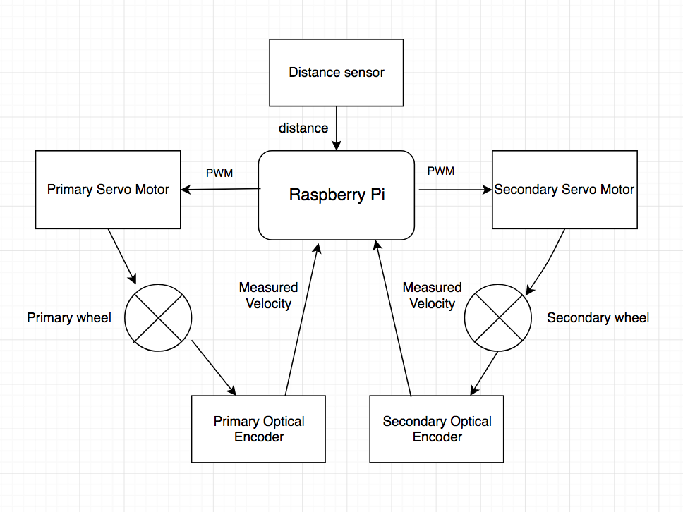
Figure 1. Overall block diagram
Objective
There are several cases wherein a robot is required to navigate in an environment where there are no external reference points to aid in determining the location or the orientation of the robot. Hence, we decided to implement such a robot using precise motions using on board sensors that did not receive any information from the environment to navigate through a 4x4 grid.
Design and Testing
The robot’s design can be broken down into 4 distinct parts:
- The physical structure
- Servo motors and wheels
- Optical encoders and encoder disk
- PID control
- Speed control
- Wheel synchronization:
The base of the robot was cut out of a sheet of acrylic which effectively was a scaled up version of the base of the ECE 5725 Lab 3 robot. The robot had two castor wheels in front which served to balance the robot and also had two plastic wheel mounts at its rear for mounting the servo motors.
Figure 2. It shows the acrylic base plate used to construct the robot
Testing: The tests were conducted on the robotic base after attaching the servo motors and wheels to it. We identified potential places where errors could originate and mitigated them such as adjusting the height of the castor wheels to ensure that the robot was resting with its weight equally divided between the front two castors.
The other problem we encountered with the physical structure during testing was that the wheels were touching the acrylic plate because the plastic wheel mounts were bending under the weight of the acrylic plate. We solved this problem by bolstering the wheel mounts with tape.
We made use of Parallax Continuous Rotation Servo Motors(#900-00008)[1] to drive the robot. From the servo motor datasheet, the spinning speed will increase when the PWM on-time decreases from 1.7ms to 1.5ms for counterclockwise rotation; the spinning speed will increase when the PWM on-time decreases from 1.5ms to 1.3ms for clockwise rotation, as shown in the figures below. We attached these motors to each of the plastic wheel mounts with the help of machined nuts and bolts. Additionally, we connected wheels to the servo motors to help the robot move. Lastly, we also created maps that gave us the relationships between each motor’s PWM on time and velocity so that we could implement the PID controllers. This open loop analysis helped us obtain equations that connected the above mentioned quantities. The maps and equations are shown below.
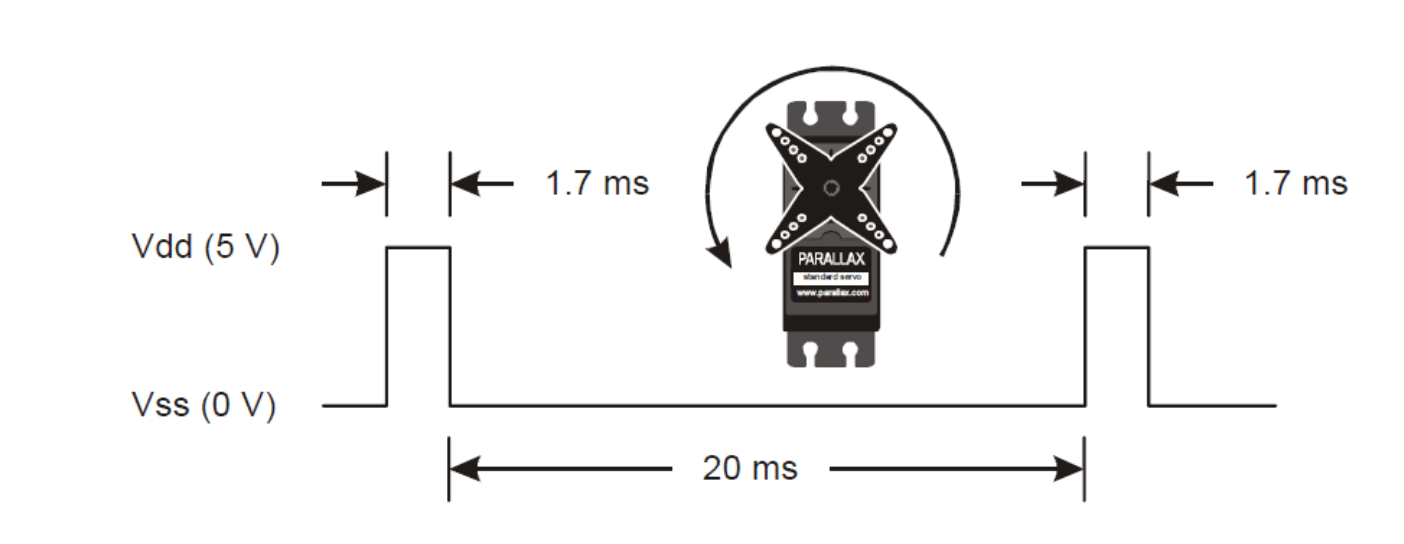
Figure 3. Servo motor counterclockwise rotation[1]
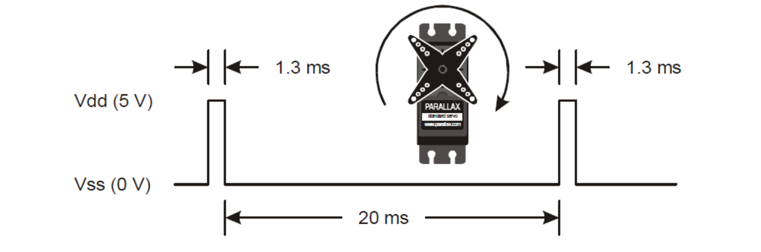
Figure 4. Servo motor clockwise rotation[1]
Table 1: Relationship between wheel velocity and PWM on-time
| Types | Wheel velocity vs PWM on-time Equation |
|---|---|
| Primary wheel counter-clockwise | On-time = 6.27 * v / 1000 + 1.51 |
| Primary wheel clockwise | On-time = -6.84 * v / 1000 + 1.5 |
| Secondary wheel counter-clockwise | On-time = -7.09 * v / 1000 + 1.49 |
| Secondary wheel clockwise | On-time = 7.54 * v / 1000 + 1.5 |
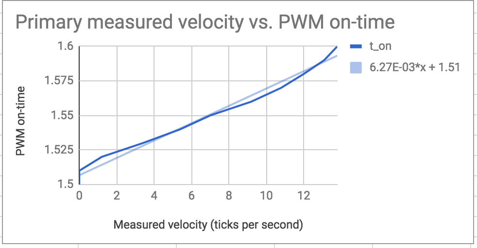
Figure 5. Measured velocity vs PWM on-time for Primary wheel counter-clockwise rotation
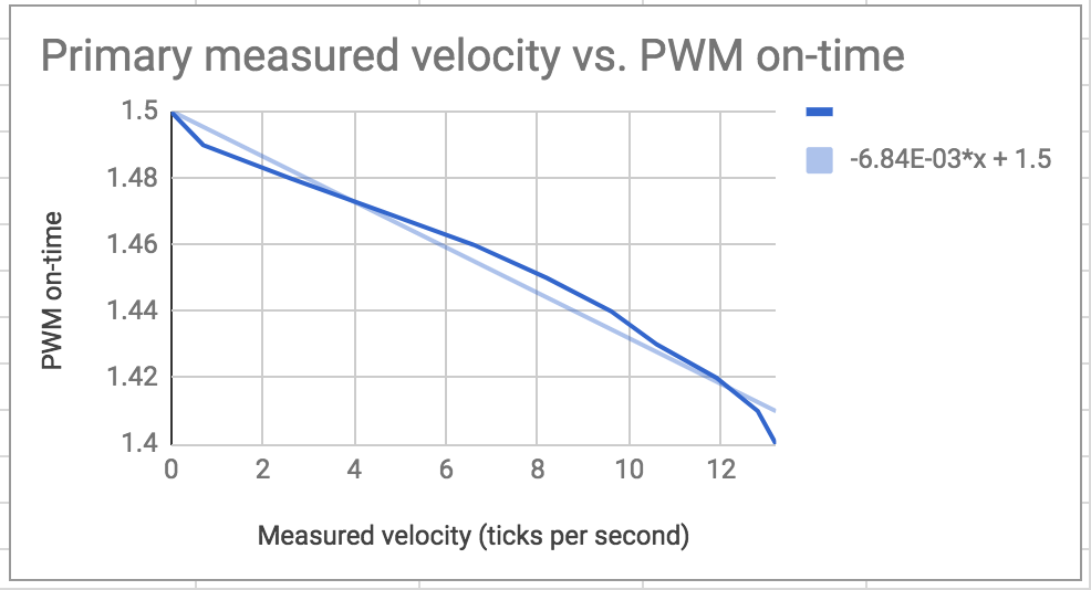
Figure 6. Measured velocity vs PWM on-time for Primary wheel clockwise rotation
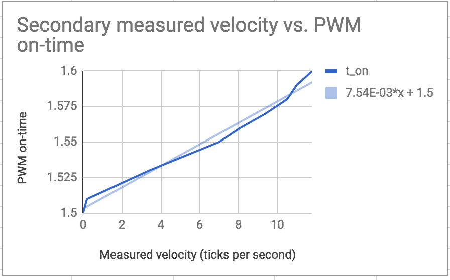
Figure 7. Measured velocity vs PWM on-time for Secondary wheel counter-clockwise rotation
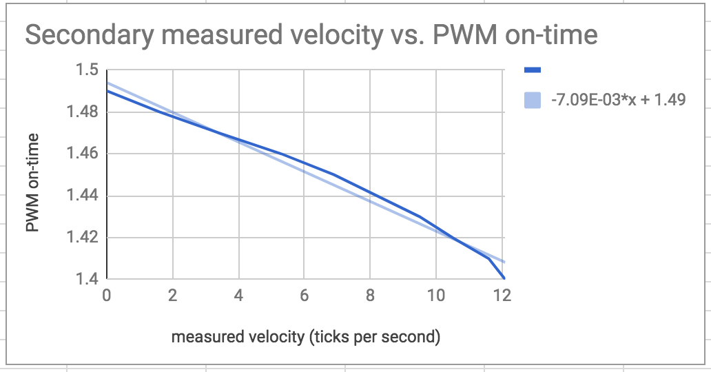
Figure 8. Measured velocity vs PWM on-time for Secondary wheel clockwise rotation
Below is a code snippet which shows how we implemented the mapping in the python code. We set PWM on-time as 20ms from datasheet, and give the function an updated velocity. We get the PWM on-time from the equation and expect the velocity to change.
# primary wheel clockwise motion feedback function
			def primary_clockwise_motor_signals(v):
				global primary_t_on, primary_t_off, primary_period, primary_freq, primary_duty
				primary_t_on = ((-6.84*v/1000) + 1.5)/1000
				primary_t_off = 20.0/1000
				primary_period =primary_t_on + primary_t_off
				primary_freq = 1/primary_period
				primary_duty = 1000000*(primary_t_on/primary_period)
				pi_hw.hardware_PWM(13,primary_freq,primary_duty)
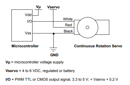
Figure 9: Servo motor wiring [1]
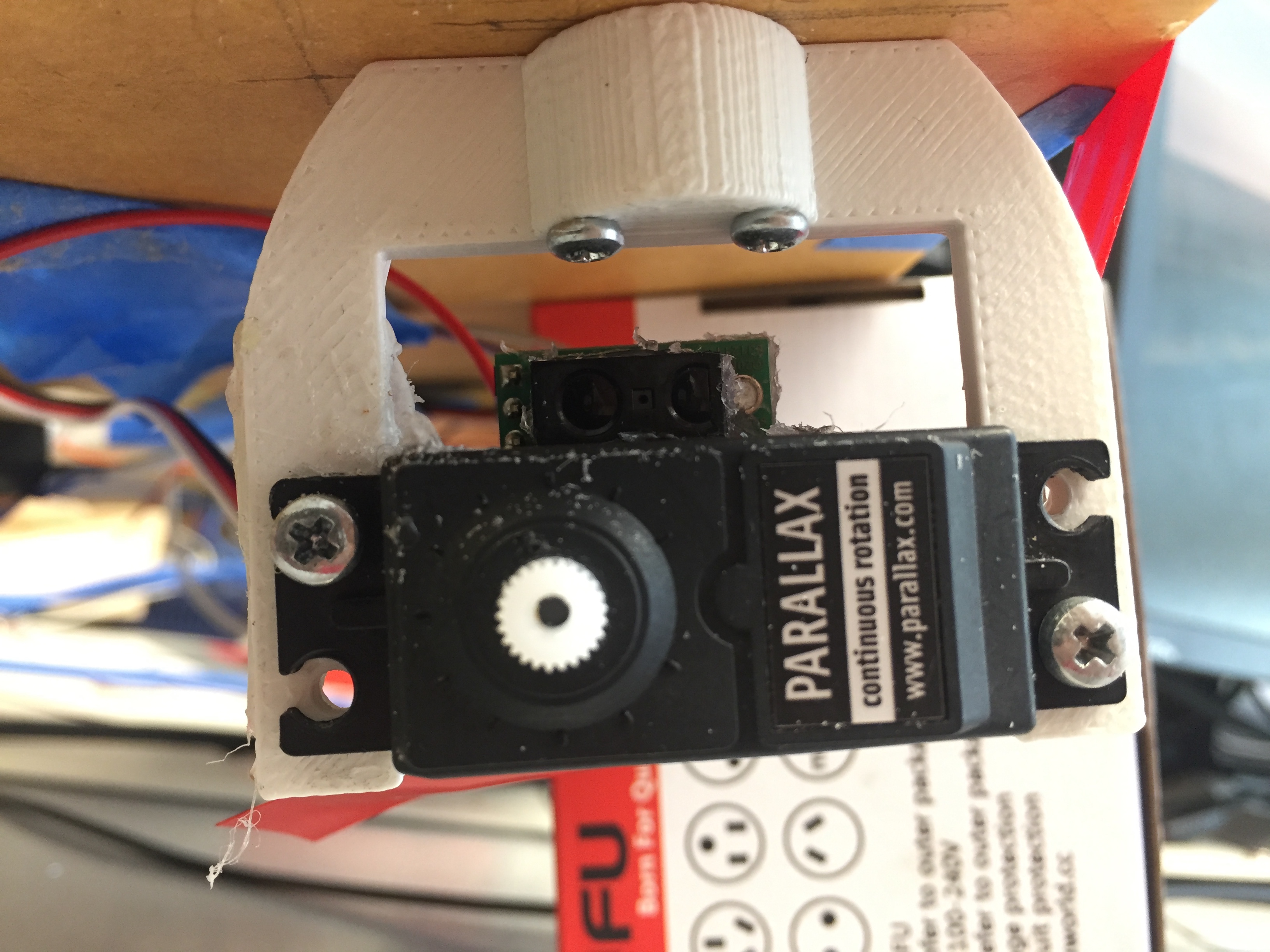
Figure 10: The servo motor bolstered with the help of the red tape
Testing: We powered on the servo motors by connecting the power to an external 6 volt power supply and linking the grounds of the power supply and the R-Pi as suggested in the datasheet. We then generated a PWM in software and sent it to the control signal of the R-Pi to test its functionality. We discovered here that the R-Pi’s non real time behaviour led to the generation of unstable PWMs in terms of the frequency and duty cycle. In order to fix this issue we changed the way in which we were generating the PWM from software to hardware by using the R-Pi’s hardware co-processor. This gave us accurate PWM signals for motor control. Additionally, we also had to calibrate the servo motors prior to implementing the PID control so that we could obtain deterministic results in terms of the PWM On Time and the motor velocity. We did this by making a python script(pwm_test.py in Code Appendix section) that sent the desired calibration signal to the control signal of each motor and physically adjusting the screw inside the servo motor.
To implement the encoder pattern detection, initially we used the holes on the wheels. Since the holes on the wheels can provide an accurate distance gap, it is easy for the optical encoder to generate a steady and consistent speed measurement. We attached white tapes on the holes on the wheels so that they can appear white while the framework of the wheel stay black as the encoder disk pattern. Then we glued the optical encoders right above the servo motors, pointing outward to the encoder disk side on the wheels. It worked as expected and can give us a reliable measurement but did not give us the desired resolution. For example, given the encoder disk pattern, it could only provide us a resolution of 3 holes per second. It was good but not enough for our PID controllers to respond. Therefore, after researching and consulting, we decided to switch to a general encoder disk which has black and white straps in between as shown on the figure below. The new encoder disk give us more resolution in term of measurement and the resolution increased up to 10 turns per second.
We also encountered a problem with the wheels of the robot wherein the wheels of the robot would slip. This was happening because the weight of the robot was too large and there were countless dust on the floor. In order to solve this issue, we first tried wrapping the wheels with wide rubber bands. However, the rubber bands would become loose and deteriorate, preventing us from using them as a robust solution. Ultimately, we moved onto using abrasive anti-slip tape[2] on both wheels. The tape offered enough traction to prevent the wheels from skidding while going straight.
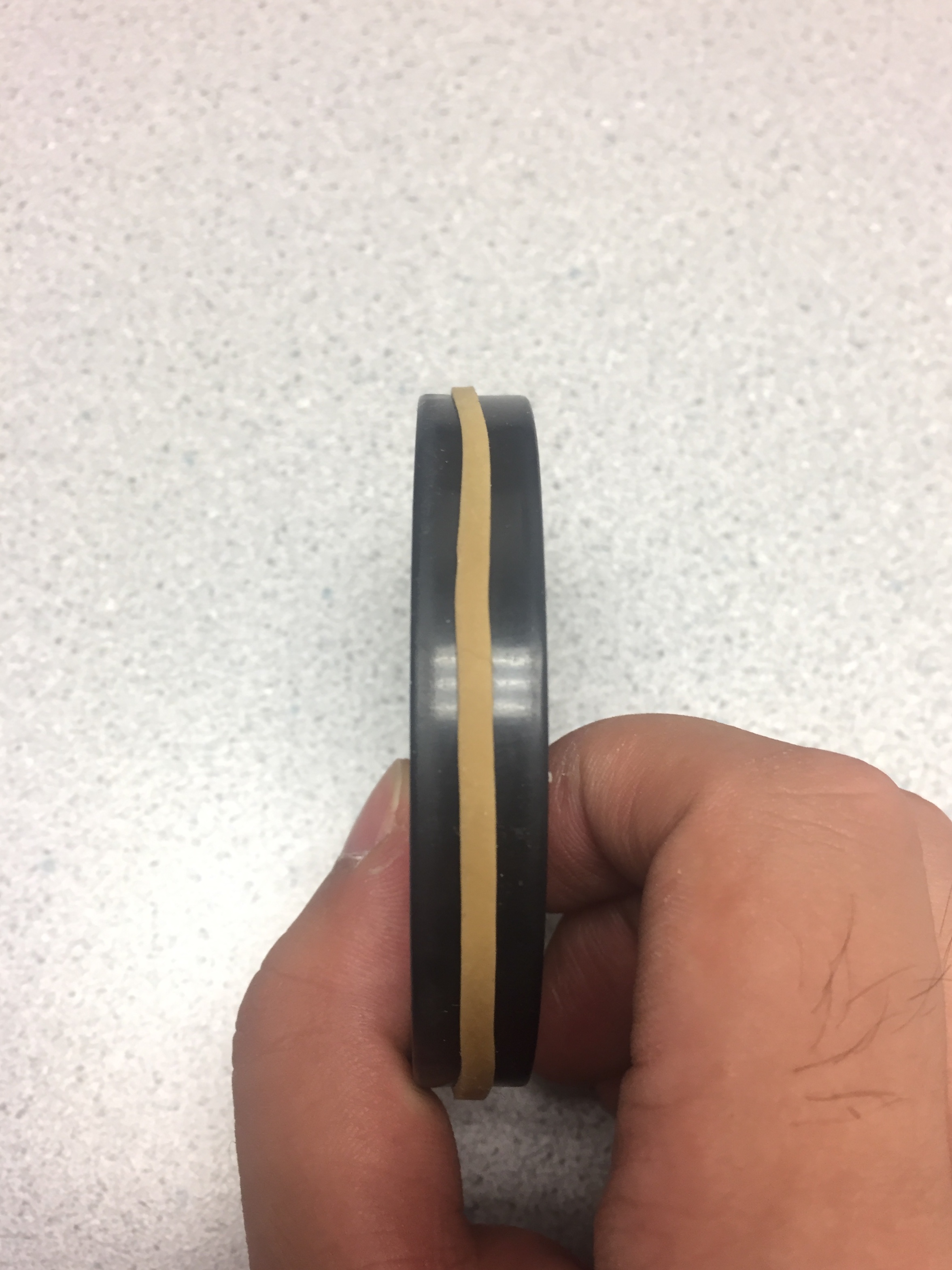
Figure 11: Rubber band on wheel for increased traction
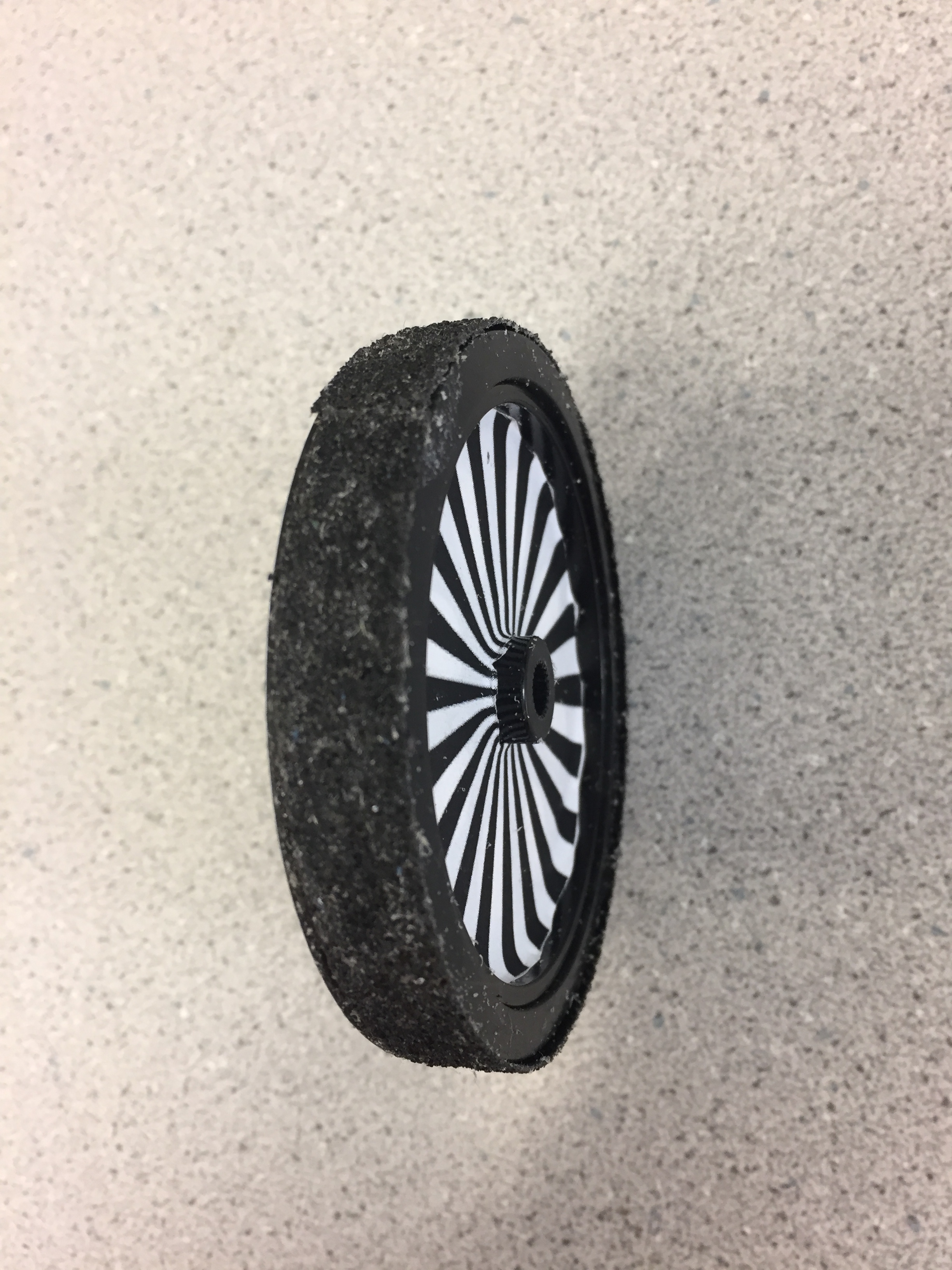
Figure 12: Anti slip tape
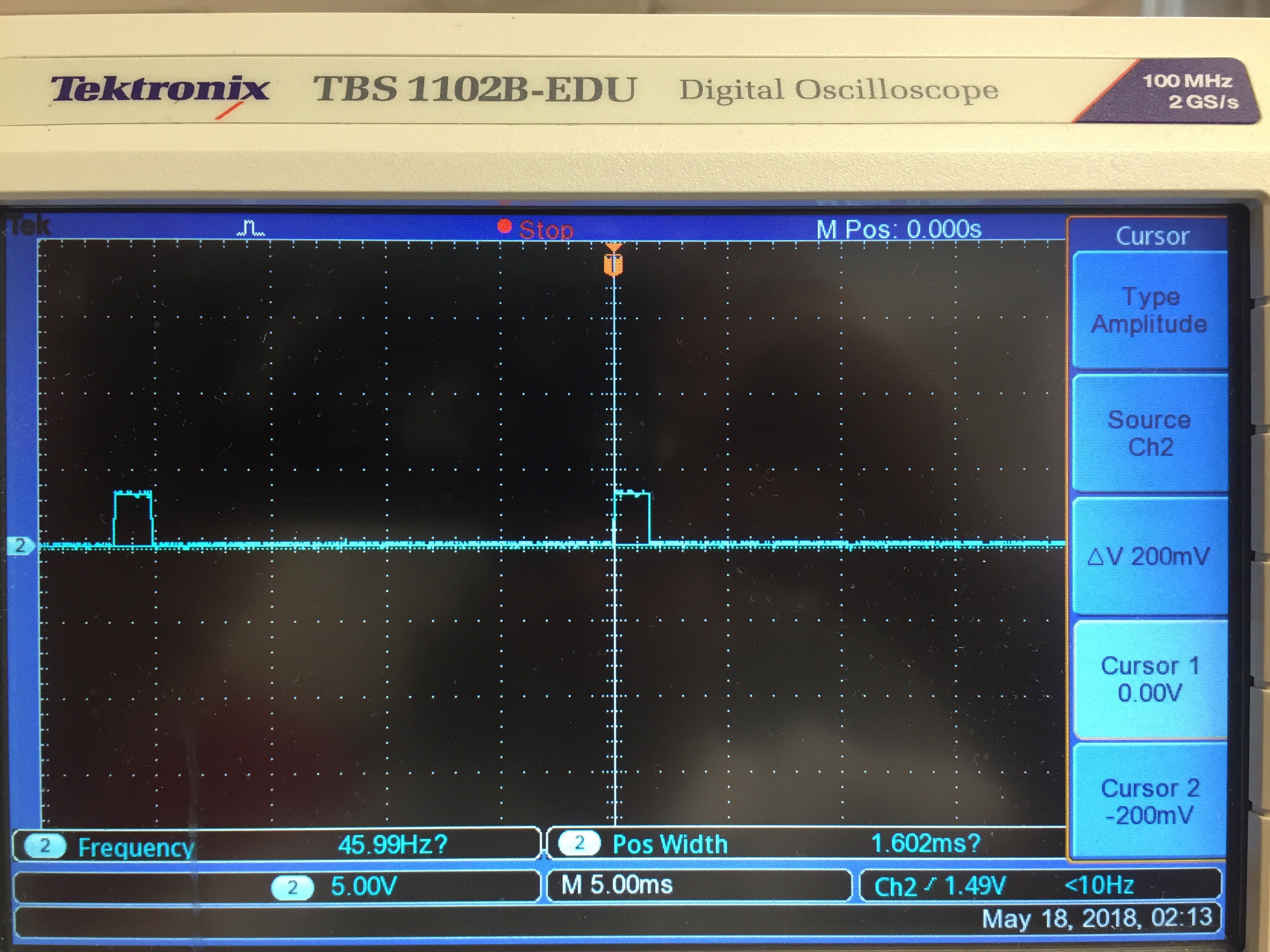
Figure 13: Servo motors control signal
Lastly, we powered the servo motors using an external battery pack. We did this because we wanted an uninterrupted power supply for the R-Pi. When the motors start moving, they draw a significant amount of current which reduces the voltage of the battery. If this battery were also connected to the R-Pi, the drop in voltage could be large enough to momentarily turn the R-Pi off.
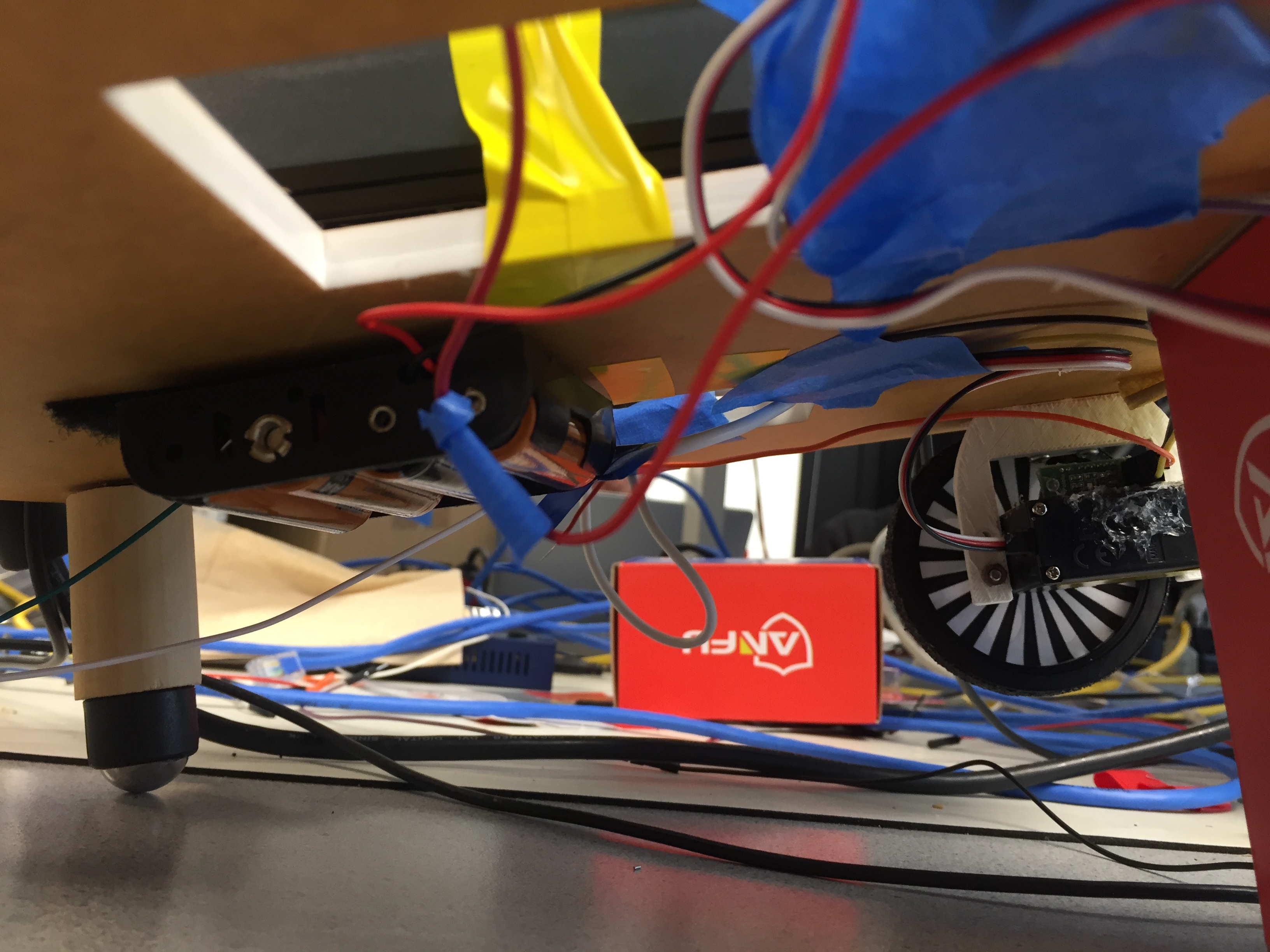
Figure 14: Battery for the servo motors
In order for us to keep track of the robot’s orientation and position without making use of external references such as distance from walls, we made use of Pololu optical encoders[3]. These were essentially distance sensors which measured if they saw an obstruction in their region of operation. These sensors gave us the velocity of each wheel.
Testing: We mounted the optical encoder directly onto the servo motors and initially made use of the holes in the wheels to measure obstruction. We covered the outer side of the wheel using white tape so that it formed a “wall” which would block the signal from the optical encoder. It gave us a reading every time there was a transition in the reflecting surface i.e. whenever the optical encoder saw that the reflection surface changed from the wheel to the white tape that was attached in the background. This gave us slightly unstable readings which is why we added debounce time in our program so that we could capture when the wheel was actually turning. However, as we progressed with the PID controllers, we realized that the resolution we were getting from the taped wheel was not enough which is why we opted to go for an encoder disk. Upon doing so, we ran into another problem because the optical encoder was unable to detect any transitions. To solve this issue, we kept altering the distance and the angle of the optical encoder from the encoder disk till we obtained a clean and stable signal. We repeated this process for the other optical encoder as well to get both of them to function properly.
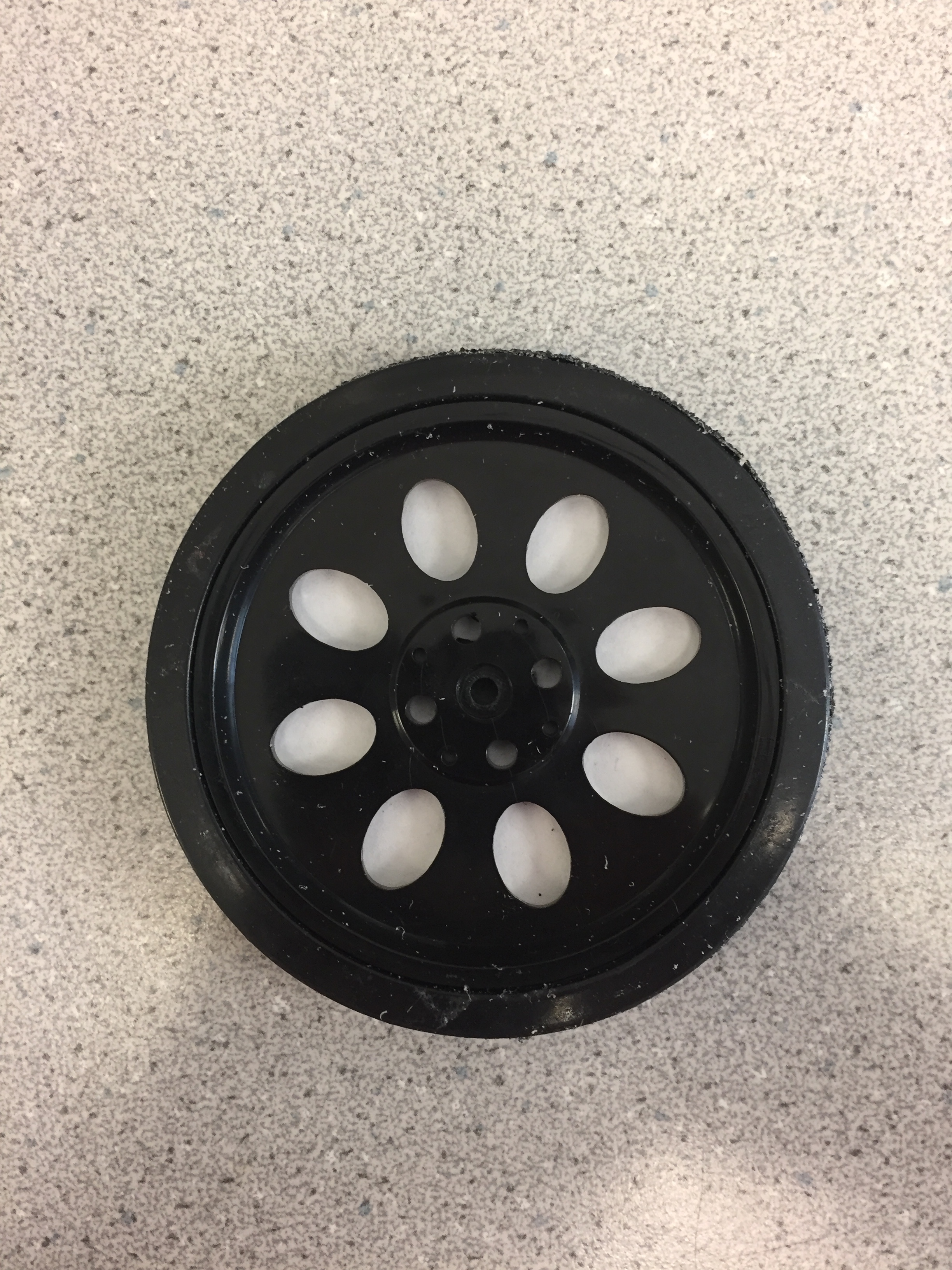
Figure 15: Wheel without encoder disk (The holes in the wheel were being used for encoder transitions)
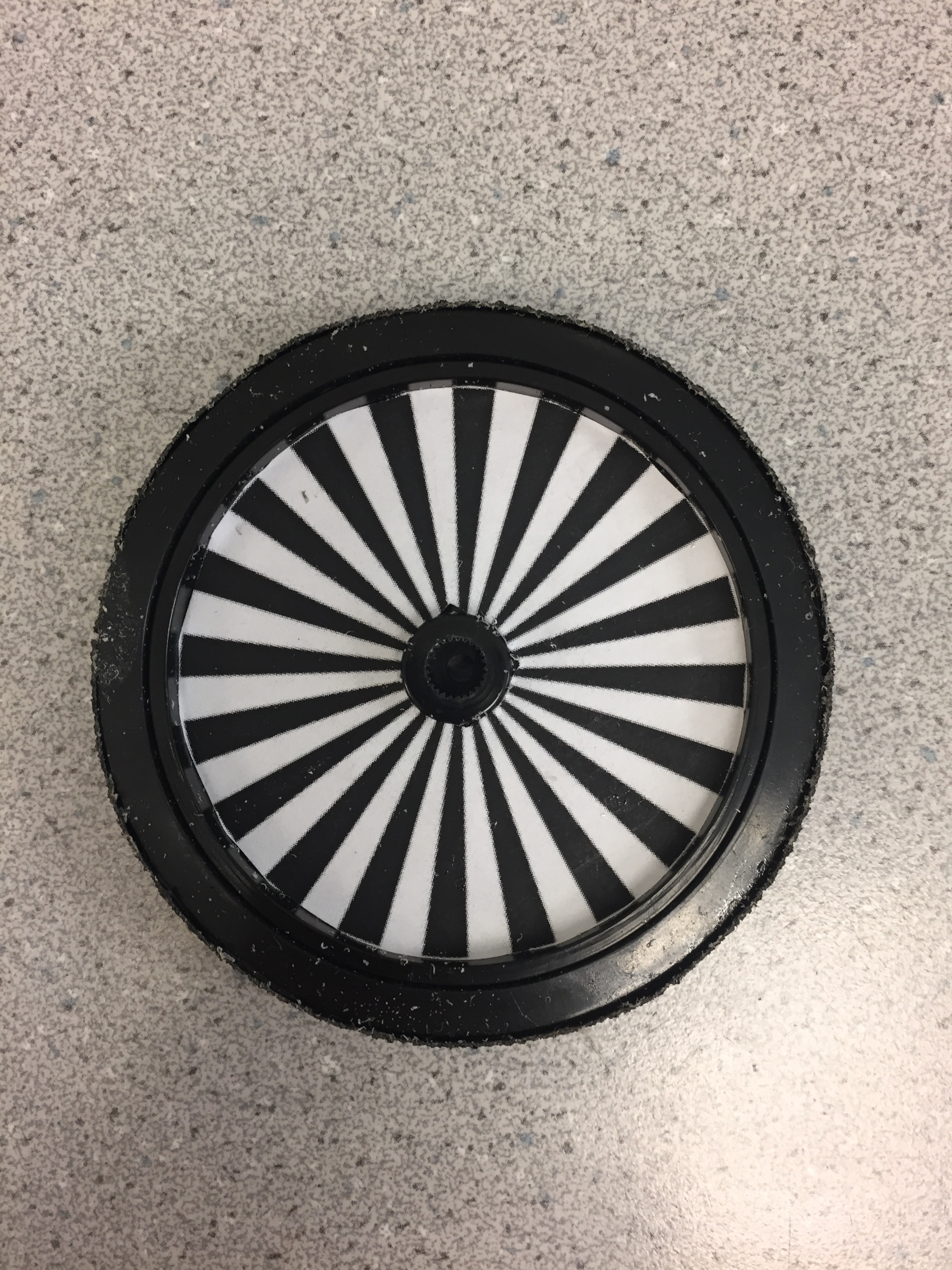
Figure 16: Wheel with encoder disk
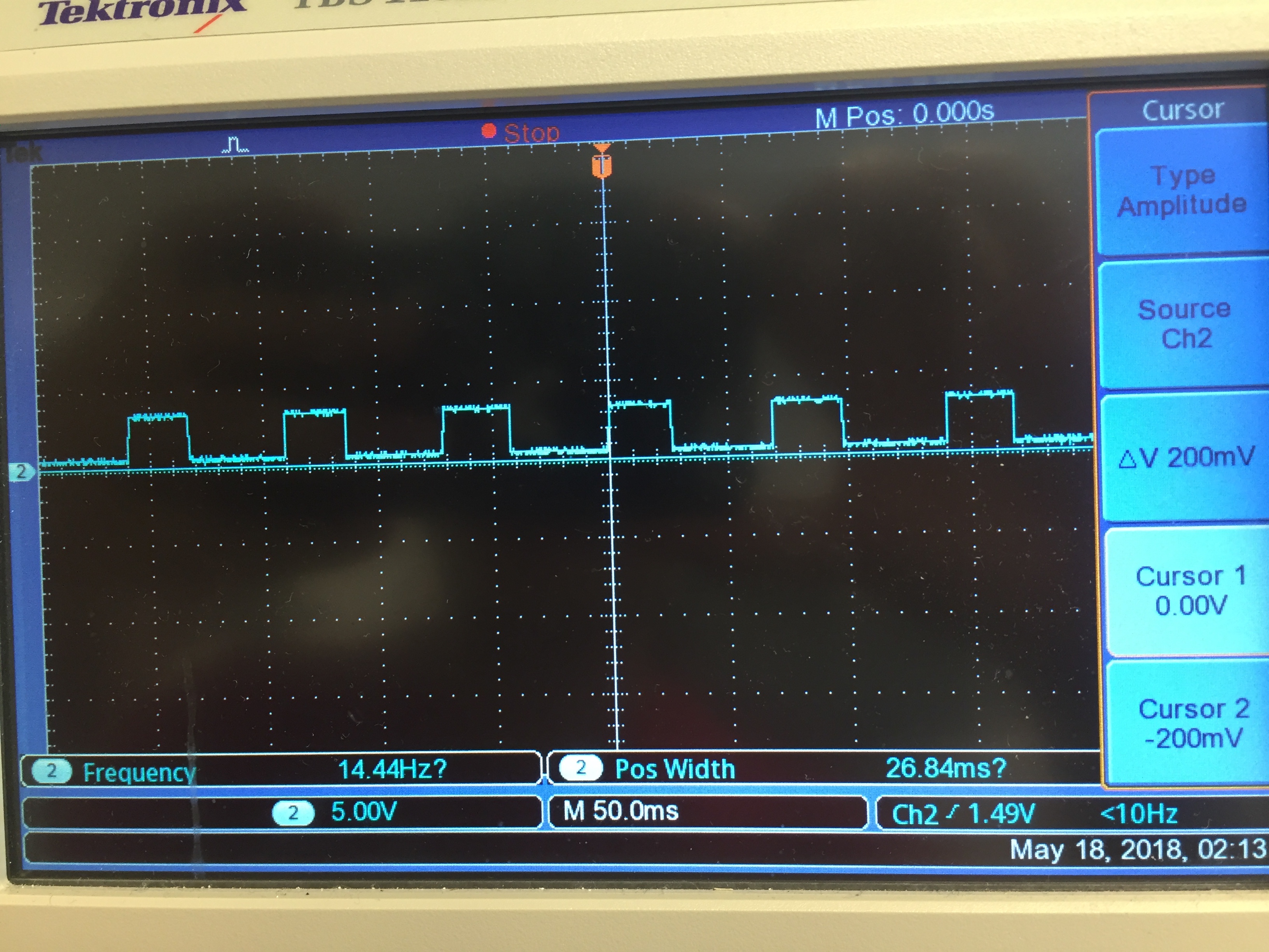
Figure 17: Optical encoder readings
To make sure that we could control the robot’s orientation and location, we made use of PID controllers. We needed to make the robot travel at a fixed speed throughout and also needed to make both the wheels of the robot turn at the same speed so that the robot travelled in a straight line. [5]
The first PID control that we implemented was for the left wheel (denoted as the primary wheel from here on), to control its velocity. The velocity of the primary wheel was being maintained by first reading the velocity of the wheel and checking if it was spinning at the desired speed. If there was a variation in the measured speed and the desired speed, the difference in speed was used in the PID equation to generate the new velocity. This new velocity was then transformed to the PWM on-time using our velocity to PWM on-time mapping we generated earlier, thereby controlling the speed of the motor. The P term, by itself, proved to generate accurate control.
Testing: We first tested this module by applying random external forces to the wheel and measuring the velocity trend afterwards. We tuned the P term till we were able to reduce the overshoot in velocity and settling time to the reference velocity.
primary_P = (v_primary_measured-v_primary_ref)
delta_v_primary = primary_P*primary_kp
v_primary_updated = v_primary_updated - delta_v_primary
primary_counter_clockwise_motor_signals(v_primary_updated)
We implemented the second PID controller so that the secondary wheel (right wheel) followed the primary wheel. It kept track of the measured velocity of the primary wheel and the measured velocity of the secondary wheel and if there was a variation in the two values, it made use of the PID equation to generate a adjustment velocity. This was transformed into the PWM on time for the secondary motor and its velocity was adjusted.
Testing: We tested the this by randomly applying forces to the primary wheel and observing the velocity response of the secondary wheel. We tuned the P term, which was the only term required, till we achieved acceptable overshoot and settling time for the motor velocity.
secondary_P = (v_secondary_measured-v_primary_measured)
delta_v_secondary = secondary_P*secondary_kp
v_secondary_updated = v_secondary_updated - delta_v_secondary
secondary_clockwise_motor_signals(v_secondary_updated)
Result
We managed to design, build and test the robot to move as instructed. However, the robot needed to be manually adjusted every time it turned but apart from that, it was able to traverse the rectangular area fairly well. Hence, the robot performed closely in accordance with our initial objective.
Conclusion
This robot was a fairly complex build since it required to be able to traverse a fixed rectangular area without using an external reference points in the environment. It’s functionality had high fidelity while going straight but needed slight manual adjustment during turning. This project serves as a versatile base for a plethora of applications such as cleaning robots.
Work Distribution
Abhimanyu Khandelwal
ak2455@cornell.edu
PID algorithm design, hardware assembly,implementation, report
Weiyou Dai
wd248@cornell.edu
PID algorithm design,implementation, debug, report
Parts List
- Raspberry Pi $35.00
- Servo motors (From Professor Skovira) $26.00
- Optical encoders $10.00
- Acrylic base plate $6.00
- Nuts, bolts, screws and tape(From Professor Skovira) $3.00
- Protoboard (From Professor Skovira) $3.00
- Solder board (From Professor Skovira) $2.00
- Wheel mounts (From Professor Skovira ) $2.00
- Wires and connectors $2.00
- Encoder disks $0.5
Total: $89.5
Future Work
We encountered a few issues which led to the non-ideal performance of the robot. Hence, if we had more time, we could have worked on solving the following issues:
The primary issue we faced was due to the floor’s imperfections. If the floor was perfectly flat and identical in the testing area, it is possible that our results would have been significantly better. Hence, it is possible and likely that running the robot on a perfectly flat surface would make the below mentioned issues irrelevant.
- Wheel skid while turning:
- Voltage drop:
- Non-identical castors:
- Obstruction sensor:
The wheels did skid while the robot was making a turn which made the robot loose its fine tuned location tracking. We could reduce the speed of the motors which would have mitigated this issue.
Whenever the wheels moved, the current drawn by the motor led to a decrease in the battery voltage. There is a chance that this could have affected the map we had created to relate the velocity and the PWM on time. We would have liked to run more tests using a stable external supply to see if this was truly affecting the wheel velocity significantly.
The castors were non-identical and could have contributed to the imperfect motion of the robot. We could have tried to make use of more identical castors.
We had worked on the ultrasonic distance sensor [4] and had got it to determine the distance to the obstacle. However, we did not implement it in the final design due to time constraints.
References
Anon, (2018). [ebook] Available at: https://www.parallax.com/sites/default/files/downloads/900-00008-Continuous-Rotation-Servo-Documentation-v2.2.pdf [Accessed 18 May 2018].
Lowes. (2018). [online] Available at: https://www.lowes.com/pd/SKID-GUARD-Reflective-Mineral-Abrasive-Anti-Slip-Tape/3185621 [Accessed 18 May 2018].
"Pololu Carrier with Sharp GP2Y0D810Z0F Digital Distance Sensor 10cm", Pololu.com, 2018. [Online]. Available: https://www.pololu.com/product/1134. [Accessed: 18- May- 2018].
U. HC-SR04, "Ultrasonic Sensor - HC-SR04 - SEN-13959 - SparkFun Electronics", Sparkfun.com, 2018. [Online]. Available: https://www.sparkfun.com/products/13959. [Accessed: 18- May- 2018].
"How to Build a Robot Tutorials - Society of Robots", Societyofrobots.com, 2018. [Online]. Available: http://www.societyofrobots.com/sensors_encoder.shtml. [Accessed: 18- May- 2018].
Code Appendix
PWM CALIBRATION CODE

pwm_test.py

# Reboot and run this file to ensure the servo control signals are correct
# This code calibrates the wheel by creating a HW PWM
# import GPIO, sys, subprocess, time packages and other libraries
import RPi.GPIO as GPIO
import time
import pigpio
import sys
import subprocess


# Setup the mode to match the mode on Broadcom pin labels
GPIO.setmode(GPIO.BCM)


# Initiating HW PWM
pi_hw = pigpio.pi()


#Primary wheel inputs to set initial speed
primary_t_on = 1.5/1000
primary_t_off = 20.0/1000
primary_period =primary_t_on + primary_t_off
primary_freq = 1.0/primary_period
primary_duty = 1000000*(primary_t_on/primary_period)


# Start the PWM
pi_hw.hardware_PWM(13,primary_freq,primary_duty)

print('Frequency: '+str(primary_freq))
print('Duty: '+str(primary_duty/10000.0))

time.sleep(5)

# Stop the PWM
pi_hw.hardware_PWM(13,0,0)
pi_hw.stop()
#map.py


# This file is used to create a map between the PWM on time and the       # measured velocity
#import GPIO, sys, subprocess, time packages and other libraries
import RPi.GPIO as GPIO
import time
import pigpio


# Setup the mode to match the mode on Broadcom pin labels
GPIO.setmode(GPIO.BCM)

#setting up GPIO 26 and 13 as an inputs
GPIO.setup(19, GPIO.IN, pull_up_down=GPIO.PUD_UP)
GPIO.setup(26, GPIO.IN, pull_up_down=GPIO.PUD_UP)

# Initiating HW PWM
pi_hw = pigpio.pi()
pi_hw.set_mode(13, pigpio.OUTPUT)
pi_hw.set_mode(12, pigpio.OUTPUT)


#Primary wheel inputs to set initial speed
primary_t_on = 1.5/1000
primary_t_off = 20.0/1000
primary_period = primary_t_on + primary_t_off
primary_freq = 1/primary_period
primary_duty = 1000000*(primary_t_on/primary_period)
# Initiate HW PWM on GPIO 13
pi_hw.hardware_PWM(13,primary_freq,primary_duty)


#Secondary wheel inputs to set initial speed
secondary_t_on = 1.4/1000
secondary_t_off = 20.0/1000
secondary_period = secondary_t_on + secondary_t_off
secondary_freq = 1/secondary_period
secondary_duty = 1000000*(secondary_t_on/secondary_period)
# Initiate HW PWM on GPIO 12
pi_hw.hardware_PWM(12,secondary_freq,secondary_duty)

# Edge detection to track wheel speeds
primary_count = 0
secondary_count = 0
temp = 0


#Primary wheel encoder to track speed
def GPIO19_callback(channel):
    global primary_count
    primary_count+= 1

# Secondary wheel encoder to tack speed
def GPIO26_callback(channel):
    global secondary_count
    secondary_count+= 1


# Event to take primary optical encoder value
GPIO.add_event_detect(19, GPIO.FALLING, callback=GPIO19_callback, bouncetime=40)

# Event to take secondary optical encoder value
GPIO.add_event_detect(26, GPIO.FALLING, callback=GPIO26_callback, bouncetime=40)

# Variables to keep track of the velocity of the wheels
v_primary_avg = 0.0
v_secondary_avg = 0.0
v_primary_sum = 0.0
v_secondary_sum = 0.0
old_primary_count= 0.0
old_secondary_count= 0.0
v_secondary_measured= 0.0
v_primary_measured = 0.0
v_primary_updated = 0.0
v_secondary_updated = 0.0

t1 = time.time()
t = time.time()
program_run_time = 6.0

while(time.time() - t1 < program_run_time):
    time.sleep(0.02)

     # Keeps track of speed measurement of each wheel per second
    if(time.time()- t >= 1.0):

        # Speed measurement
        v_primary_measured = primary_count-old_primary_count
        v_secondary_measured = secondary_count-old_secondary_count

        # Taking velocity summation for averaging purposes
        v_primary_sum = v_primary_sum + v_primary_measured
        v_secondary_sum = v_secondary_sum + v_secondary_measured

        # Used to track the velocities of the wheels
        old_primary_count = primary_count
        old_secondary_count = secondary_count

        #print((time.time() - t_3))
        print("secondary = " +str(v_secondary_measured))
        #print("secondary = " + str(v_secondary_measured))

        # reset timer
        t=time.time()


# Determines average velocity of both wheels
v_primary_avg = v_primary_sum/(program_run_time - 1)
v_secondary_avg = v_secondary_sum/(program_run_time - 1)

print(v_secondary_avg)
# Sets both PWMs to zero
pi_hw.hardware_PWM(13,0,0)
pi_hw.hardware_PWM(12,0,0)

#resets GPIO config
GPIO.cleanup()

# Stops the HW coprocessor
pi_hw.stop()
PID CONTROL CODE

# wheels.py

# This code was used to create and fine tune the PID controllers for both # wheels
# import GPIO, sys, subprocess, time packages and other libraries
import RPi.GPIO as GPIO
import time
import pigpio
import sys
import subprocess


# Setup the mode to match the mode on Broadcom pin labels
GPIO.setmode(GPIO.BCM)

#setting up GPIO 26 and 13 as an inputs
GPIO.setup(19, GPIO.IN, pull_up_down=GPIO.PUD_UP)
GPIO.setup(26, GPIO.IN, pull_up_down=GPIO.PUD_UP)

# Initiating HW PWM
pi_hw = pigpio.pi()
pi_hw.set_mode(13, pigpio.OUTPUT)
pi_hw.set_mode(12, pigpio.OUTPUT)


#Primary wheel inputs to set initial speed
primary_t_on = 1.585/1000
primary_t_off = 20.0/1000
primary_period =primary_t_on + primary_t_off
primary_freq = 1/primary_period
primary_duty = 1000000*(primary_t_on/primary_period)
# Initiate HW PWM on GPIO 13
pi_hw.hardware_PWM(13,primary_freq,primary_duty)


#Secondary wheel inputs to set initial speed
secondary_t_on = 1.505/1000
secondary_t_off = 20.0/1000
secondary_period =secondary_t_on + secondary_t_off
secondary_freq = 1/secondary_period
secondary_duty = 1000000*(secondary_t_on/secondary_period)
# Initiate HW PWM on GPIO 12 pi_hw.hardware_PWM(12,secondary_freq,secondary_duty)


# variables to keep track of P gain term and encoder ticks
primary_count = 0
secondary_count = 0
temp = 0
primary_P=0
secondary_P = 0


#Primary wheel encoder
def GPIO19_callback(channel):
    global primary_count
    primary_count+= 1
# Secondary wheel encdoer
def GPIO26_callback(channel):
    global secondary_count
    secondary_count+= 1

# Feedback function for primary wheel
def velocity_to__primary_motor_control_signals(v):
    global primary_t_on, primary_t_off, primary_period, primary_freq, primary_duty
    primary_t_on = ((v+128.0)/82.6)/1000
    primary_t_off = 20.0/1000
    primary_period =primary_t_on + primary_t_off
    primary_freq = 1/primary_period
    primary_duty = 1000000*(primary_t_on/primary_period)
#   generate PWM with new frequency and duty cycle
    pi_hw.hardware_PWM(13,primary_freq,primary_duty)


# Feedback function for secondary wheel
def velocity_to__secondary_motor_control_signals(v):
    global secondary_t_on, secondary_t_off, secondary_period, secondary_freq, secondary_duty
    secondary_t_on = ((v+122.0)/82.6)/1000
    secondary_t_off = 20.0/1000
    secondary_period = secondary_t_on + secondary_t_off
    secondary_freq = 1/secondary_period
    secondary_duty = 1000000*(secondary_t_on/secondary_period)
    pi_hw.hardware_PWM(12,secondary_freq,secondary_duty)

# Event to take primary optical encoder value
GPIO.add_event_detect(19, GPIO.FALLING, callback=GPIO19_callback, bouncetime=100)

# Event to take secondary optical encoder value
GPIO.add_event_detect(26, GPIO.FALLING, callback=GPIO26_callback, bouncetime=100)

# Reference velocity of the primary wheel
v_primary_ref = 3.0
v_secondary_ref = 3.0

v_primary_measured = 0.0
old_primary_count = 0.0
old_secondary_count = 0.0
v_primary_updated = v_primary_ref
v_secondary_updated = v_secondary_ref
primary_kp = 0.02
secondary_kp = 0.01
v_primary_avg = 0.0
v_primary_sum = 0.0
v_secondary_avg = 0.0
v_secondary_sum = 0.0

# Program run time
program_run_time = 11

#One second value for counts/second
one_second = 1
start_time = time.time()
# Time delay for the Primary PID control
t = time.time()
begin_velocity_update_time = time.time()
while(time.time() - start_time < program_run_time):

    time.sleep(0.02)
    if(time.time()-t < one_second):
        # Does nothing
        temp=temp
    else:

        #print("Primary= " + str(primary_t_on*100.0))
        #print("old_primary_count= " + str(old_primary_count))

        # Speed measurement
        v_primary_measured = primary_count-old_primary_count
        v_secondary_measured = secondary_count-old_secondary_count

        # Taking velocity summation for averaging purposes
        v_primary_sum = v_primary_sum + v_primary_measured
        v_secondary_sum = v_secondary_sum + v_secondary_measured
        #v_primary_avg = v_primary_avg/(program_run_time-1)

        # Used to track the velocities of the wheels
        old_primary_count = primary_count
        old_secondary_count = secondary_count

        # Master wheel P term
        primary_P = (v_primary_measured-v_primary_ref)
        secondary_P = (v_secondary_measured-v_primary_measured)


        #print("duty= " +str(secondary_t_on))
        #print("v_secondary_measured= " +str(v_secondary_measured))
        #print("frew= " +str(primary_freq))
        #print("duty" +str(primary_t_on*1000.0))
        #print("P" +str(P))
        #print("updated v" +str(v_primary_updated))
        t=time.time()


    delta_v_primary = primary_P*primary_kp
    v_primary_updated = v_primary_updated - delta_v_primary

    delta_v_secondary = secondary_P*secondary_kp
    v_secondary_updated = v_secondary_updated + delta_v_secondary
    velocity_to__secondary_motor_control_signals(v_secondary_updated)
    # Begin Primary PID after 1.5 seconds
    if(time.time() - begin_velocity_update_time > 1.5):
        velocity_to__primary_motor_control_signals(v_primary_updated)


    #print("v_new" +str(v_primary_updated))
v_primary_avg = v_primary_sum/(program_run_time - 1)
v_secondary_avg = v_secondary_sum/(program_run_time - 1)
#print("average= " + str(v_primary_avg))

pi_hw.hardware_PWM(13,0,0)
pi_hw.hardware_PWM(12,0,0)
#resets GPIO config
GPIO.cleanup()

pi_hw.stop()
TRAVERSING CODE:

final.py

# Robot fixed area traversing code
# import GPIO, sys, subprocess, time packages and other libraries
import RPi.GPIO as GPIO
import time
import pigpio


# Setup the mode to match the mode on Broadcom pin labels
GPIO.setmode(GPIO.BCM)

#setting up GPIO 26 and 13 as an inputs
GPIO.setup(19, GPIO.IN, pull_up_down=GPIO.PUD_UP)
GPIO.setup(26, GPIO.IN, pull_up_down=GPIO.PUD_UP)

# Initiating HW PWM
pi_hw = pigpio.pi()
pi_hw.set_mode(13, pigpio.OUTPUT)
pi_hw.set_mode(12, pigpio.OUTPUT)


#Primary wheel inputs to set initial speed
primary_t_on = 1.6/1000
primary_t_off = 20.0/1000
primary_period = primary_t_on + primary_t_off
primary_freq = 1/primary_period
primary_duty = 1000000*(primary_t_on/primary_period)
pi_hw.hardware_PWM(13,primary_freq,primary_duty)


#Secondary wheel inputs to set initial speed
secondary_t_on = 1.51/1000
secondary_t_off = 20.0/1000
secondary_period = secondary_t_on + secondary_t_off
secondary_freq = 1/secondary_period
secondary_duty = 1000000*(secondary_t_on/secondary_period)
pi_hw.hardware_PWM(12,secondary_freq,secondary_duty)


# Edge detection to track wheel speeds
primary_count = 0
secondary_count = 0
temp = 0


#Primary wheel encoder to track speed
def GPIO19_callback(channel):
    global primary_count
    primary_count+= 1

# Secondary wheel encdoer to tack speed
def GPIO26_callback(channel):
    global secondary_count
    secondary_count+= 1

# primary wheel clockwise motion feedback function
def primary_clockwise_motor_signals(v):
    global primary_t_on, primary_t_off, primary_period, primary_freq, primary_duty
    primary_t_on = ((-6.84*v/1000) + 1.5)/1000
    primary_t_off = 20.0/1000
    primary_period =primary_t_on + primary_t_off
    primary_freq = 1/primary_period
    primary_duty = 1000000*(primary_t_on/primary_period)
    pi_hw.hardware_PWM(13,primary_freq,primary_duty)

# Fprimary wheel counter clockwise motion feedback function
def primary_counter_clockwise_motor_signals(v):
    global primary_t_on, primary_t_off, primary_period, primary_freq, primary_duty
    primary_t_on = ((v*7.05/1000) + 1.51)/1000
    primary_t_off = 20.0/1000
    primary_period =primary_t_on + primary_t_off
    primary_freq = 1/primary_period
    primary_duty = 1000000*(primary_t_on/primary_period)
    pi_hw.hardware_PWM(13,primary_freq,primary_duty)


# secondary wheel clockwise motion feedback function
def secondary_clockwise_motor_signals(v):
    global secondary_t_on, secondary_t_off, secondary_period, secondary_freq, secondary_duty
    secondary_t_on = ((-6.89*v/1000) + 1.49)/1000
    secondary_t_off = 20.0/1000
    secondary_period = secondary_t_on + secondary_t_off
    secondary_freq = 1/secondary_period
    secondary_duty = 1000000*(secondary_t_on/secondary_period)
    pi_hw.hardware_PWM(12,secondary_freq,secondary_duty)


# secondary wheel counter clockwise motion feedback function
def secondary_counter_clockwise_motor_signals(v):
    global secondary_t_on, secondary_t_off, secondary_period, secondary_freq, secondary_duty
    secondary_t_on = ((v*7.54/1000) + 1.5)/1000
    secondary_t_off = 20.0/1000
    secondary_period = secondary_t_on + secondary_t_off
    secondary_freq = 1/secondary_period
    secondary_duty = 1000000*(secondary_t_on/secondary_period)
    pi_hw.hardware_PWM(12,secondary_freq,secondary_duty)

# Event to take primary optical encoder value
GPIO.add_event_detect(19, GPIO.FALLING, callback=GPIO19_callback, bouncetime=40)

# Event to take secondary optical encoder value
GPIO.add_event_detect(26, GPIO.FALLING, callback=GPIO26_callback, bouncetime=40)

# Reference velocity of the wheels
v_primary_ref = 9.0
v_secondary_ref = v_primary_ref


# variable list

# Measures primary wheel velocity
v_primary_measured = 0.0
old_primary_count = 0.0

# Measures secondary wheel velocity
v_secondary_measured = 0.0
old_secondary_count = 0.0

# Updated velocities to keep track of PID controller
v_primary_updated = v_primary_ref
v_secondary_updated = v_secondary_ref

# P gain value for constant speed
primary_kp = 0.005

# P gain value for straight line motion
secondary_kp = 0.0076

# Used to measure the average velocity of wheels
v_primary_avg = 0.0
v_primary_sum = 0.0
v_secondary_avg = 0.0
v_secondary_sum = 0.0

#One second value for counts/second
one_second = 1.0

# Initailizing P term for both PID controllers
primary_P = 0
secondary_P = 0


# Mapping of the travesing area
horizontal_grid_counter = 1
vertical_grid_counter = 0

#########################

program_run_time = 250
start_time = time.time()
########################


# Turn direction
turn_indicator = False


# Sanitizaion time
wait_time = 5

# Time delay for the Primary PID control
t = time.time()
t_3 = time.time()
t_30 = time.time()
# Time delay for implementing the PID controller for constant speed
begin_velocity_update_time = time.time()


while((horizontal_grid_counter <= 4) and (time.time() - start_time < program_run_time)):

    time.sleep(0.02)

    # Keeps track of speed measurement of each wheel per second
    if(time.time()- t >= one_second):

        # Speed measurement
        v_primary_measured = primary_count-old_primary_count
        v_secondary_measured = secondary_count-old_secondary_count

        # Taking velocity summation for averaging purposes
        v_primary_sum = v_primary_sum + v_primary_measured
        v_secondary_sum = v_secondary_sum + v_secondary_measured

        # Used to track the velocities of the wheels
        old_primary_count = primary_count
        old_secondary_count = secondary_count

        #print((time.time() - t_3))
        print("left = " +str(v_primary_measured))
        print("right = " + str(v_secondary_measured))
       # print("second t on" +str(secondary_t_on*1000))
        print("")
        # reset timer
        t=time.time()


    if(vertical_grid_counter < 5):

        # straight line travel for 3 seconds
        if(time.time() - t_3 < 2.2):
            # Both wheel P term
            primary_P = (v_primary_measured-v_primary_ref)
            secondary_P = (v_secondary_measured-v_primary_measured)

            delta_v_primary = primary_P*primary_kp
            v_primary_updated = v_primary_updated - delta_v_primary

            delta_v_secondary = secondary_P*secondary_kp
            v_secondary_updated = v_secondary_updated - delta_v_secondary
            secondary_clockwise_motor_signals(v_secondary_updated)
            # Begin Primary PID after 1.5 seconds
           # if(time.time() - begin_velocity_update_time > 1.0):
            primary_counter_clockwise_motor_signals(v_primary_updated)
        # wait for 30 seconds
        elif((time.time() - t_3 >= 2.2) and (time.time() - t_3 <= wait_time +2.2)):
            pi_hw.hardware_PWM(13,0,0)
            pi_hw.hardware_PWM(12,0,0)
        # reset timer and update counter
        else:
            vertical_grid_counter = vertical_grid_counter + 1
            t_3 = time.time()


    else:
        if(not(turn_indicator)):
            # straight line travel for 3 seconds
            if(time.time() - t_3 < 2.2):
                # Both wheel P term
                primary_P = (v_primary_measured-v_primary_ref)
                secondary_P = (v_secondary_measured-v_primary_measured)
                delta_v_primary = primary_P*primary_kp
                delta_v_secondary = secondary_P*secondary_kp


                v_primary_updated = v_primary_updated + delta_v_primary
                v_secondary_updated = v_secondary_updated - delta_v_secondary
                primary_clockwise_motor_signals(v_primary_updated)
                secondary_clockwise_motor_signals(v_secondary_updated)
                print('left')


            elif((time.time() - t_3 >= 2.2) and (time.time() - t_3 <= 5.2)):
                pi_hw.hardware_PWM(13,0,0)
                pi_hw.hardware_PWM(12,0,0)

            # reset timer and update counter
            elif((time.time() - t_3 > 5.2) and (time.time() - t_3 < 6.7)):

                print('straight')
                 # Both wheel P term
                primary_P = (v_primary_measured-v_primary_ref)
                secondary_P = (v_secondary_measured-v_primary_measured)

                delta_v_primary = primary_P*primary_kp
                v_primary_updated = v_primary_updated - delta_v_primary

                delta_v_secondary = secondary_P*secondary_kp
                v_secondary_updated = v_secondary_updated - delta_v_secondary
                secondary_clockwise_motor_signals(v_secondary_updated)
                # Begin Primary PID after 1.5 seconds
                if(time.time() - begin_velocity_update_time > 1):
                    primary_counter_clockwise_motor_signals(v_primary_updated)


            elif((time.time() - t_3 >= 6.7) and (time.time() - t_3 <= 9.7)):
                pi_hw.hardware_PWM(13,0,0)
                pi_hw.hardware_PWM(12,0,0)

            elif((time.time() - t_3 > 9.7) and (time.time() - t_3 < 12.0)):
                # Both wheel P term
                primary_P = (v_primary_measured-v_primary_ref)
                secondary_P = (v_secondary_measured-v_primary_measured)
                delta_v_primary = primary_P*primary_kp
                delta_v_secondary = secondary_P*secondary_kp


                v_primary_updated = v_primary_updated + delta_v_primary
                v_secondary_updated = v_secondary_updated - delta_v_secondary
                primary_clockwise_motor_signals(v_primary_updated)
                secondary_clockwise_motor_signals(v_secondary_updated)


            elif((time.time() - t_3 >= 12) and (time.time() - t_3 <= 15)):
                pi_hw.hardware_PWM(13,0,0)
                pi_hw.hardware_PWM(12,0,0)

            elif((time.time() - t_3 > 15) and (time.time() - t_3 < 15.9)):

                print('straight')
                # Both wheel P term
                primary_P = (v_primary_measured-v_primary_ref)
                secondary_P = (v_secondary_measured-v_primary_measured)

                delta_v_primary = primary_P*primary_kp
                v_primary_updated = v_primary_updated - delta_v_primary

                delta_v_secondary = secondary_P*secondary_kp
                v_secondary_updated = v_secondary_updated - delta_v_secondary
                secondary_clockwise_motor_signals(v_secondary_updated)
                # Begin Primary PID after 1.5 seconds
                if(time.time() - begin_velocity_update_time > 1):
                    primary_counter_clockwise_motor_signals(v_primary_updated)

            elif((time.time() - t_3 >=15.9) and (time.time() - t_3 <= 15.9 + wait_time)):
                pi_hw.hardware_PWM(13,0,0)
                pi_hw.hardware_PWM(12,0,0)

            else:
                t_3 = time.time()
                vertical_grid_counter = 1
                horizontal_grid_counter = horizontal_grid_counter + 1
                turn_indicator = not(turn_indicator)

        elif(turn_indicator):
             # straight line travel for 3 seconds
            if(time.time() - t_3 < 1.6):
                # Both wheel P term
                primary_P = (v_primary_measured-v_primary_ref)
                secondary_P = (v_secondary_measured-v_primary_measured)
                delta_v_primary = primary_P*primary_kp
                delta_v_secondary = secondary_P*secondary_kp


                v_primary_updated = v_primary_updated - delta_v_primary
                v_secondary_updated = v_secondary_updated + delta_v_secondary
                primary_counter_clockwise_motor_signals(v_primary_updated)
                secondary_counter_clockwise_motor_signals(v_secondary_updated)
                print('right')


            elif((time.time() - t_3 >= 1.6) and (time.time() - t_3 <= 4.6)):
                pi_hw.hardware_PWM(13,0,0)
                pi_hw.hardware_PWM(12,0,0)

            # reset timer and update counter
            elif((time.time() - t_3 > 4.6) and (time.time() - t_3 <5.9)):

                print('straight')
                 # Both wheel P term
                primary_P = (v_primary_measured-v_primary_ref)
                secondary_P = (v_secondary_measured-v_primary_measured)

                delta_v_primary = primary_P*primary_kp
                v_primary_updated = v_primary_updated - delta_v_primary

                delta_v_secondary = secondary_P*secondary_kp
                v_secondary_updated = v_secondary_updated - delta_v_secondary
                secondary_clockwise_motor_signals(v_secondary_updated)
                # Begin Primary PID after 1.5 seconds
                if(time.time() - begin_velocity_update_time > 1):
                    primary_counter_clockwise_motor_signals(v_primary_updated)


            elif((time.time() - t_3 >= 5.9) and (time.time() - t_3 <= 8.9)):
                pi_hw.hardware_PWM(13,0,0)
                pi_hw.hardware_PWM(12,0,0)

            elif((time.time() - t_3 > 8.9) and (time.time() - t_3 < 10.5)):
                # Both wheel P term
                primary_P = (v_primary_measured-v_primary_ref)
                secondary_P = (v_secondary_measured-v_primary_measured)
                delta_v_primary = primary_P*primary_kp
                delta_v_secondary = secondary_P*secondary_kp


                v_primary_updated = v_primary_updated - delta_v_primary
                v_secondary_updated = v_secondary_updated + delta_v_secondary
                primary_counter_clockwise_motor_signals(v_primary_updated)
                secondary_counter_clockwise_motor_signals(v_secondary_updated)

            elif((time.time() - t_3 >= 10.5) and (time.time() - t_3 <= 13.5)):
                pi_hw.hardware_PWM(13,0,0)
                pi_hw.hardware_PWM(12,0,0)

            elif((time.time() - t_3 > 13.5) and (time.time() - t_3 < 14.9)):

                print('straight')
                # Both wheel P term
                primary_P = (v_primary_measured-v_primary_ref)
                secondary_P = (v_secondary_measured-v_primary_measured)

                delta_v_primary = primary_P*primary_kp
                v_primary_updated = v_primary_updated - delta_v_primary

                delta_v_secondary = secondary_P*secondary_kp
                v_secondary_updated = v_secondary_updated - delta_v_secondary
                secondary_clockwise_motor_signals(v_secondary_updated)
                # Begin Primary PID after 1.5 seconds
                if(time.time() - begin_velocity_update_time > 1):
                    primary_counter_clockwise_motor_signals(v_primary_updated)

            elif((time.time() - t_3 >=14.9) and (time.time() - t_3 <= 14.9 + wait_time)):
                pi_hw.hardware_PWM(13,0,0)
                pi_hw.hardware_PWM(12,0,0)

            else:
                t_3 = time.time()
                vertical_grid_counter = 1
                horizontal_grid_counter = horizontal_grid_counter + 1
                turn_indicator = not(turn_indicator)


# Determines average velocity of both wheels
v_primary_avg = v_primary_sum/(program_run_time - 1)
v_secondary_avg = v_secondary_sum/(program_run_time - 1)

# Sets both PWM's to zero
pi_hw.hardware_PWM(13,0,0)
pi_hw.hardware_PWM(12,0,0)

#resets GPIO config
GPIO.cleanup()

# Stops the HW coprocessor
pi_hw.stop()