Auto Lane-Changing Robot
Tianfang Liu (tl697), Liming Yang (ly337)
Introduction
Nowadays autonomous driving has become the big trend in the automotive industry. Some modern cars have integrated the lane keeping assist into their cruise control function. Our final design project expanded that and achieved a more advanced lane keeping and changing assist system. The project aims to simulate the real-life highway situation and we designed an auto robot car based on Raspberry Pi, which could perform auto lane-changing, safe distance keeping and auto lane-keeping. The algorithm is implemented in Python and ultrasonic distance sensors and infrared line followers are used in our robot.
Objective
Lorem ipsum dolor sit amet, consectetur adipisicing elit, sed do eiusmod tempor incididunt ut labore et dolore magna aliqua. Ut enim ad minim veniam, quis nostrud exercitation ullamco laboris nisi ut aliquip ex ea commodo consequat. Duis aute irure dolor in reprehenderit in voluptate velit esse cillum dolore eu fugiat nulla pariatur. Excepteur sint occaecat cupidatat non proident, sunt in culpa qui officia deserunt mollit anim id est laborum.
Design and Testing
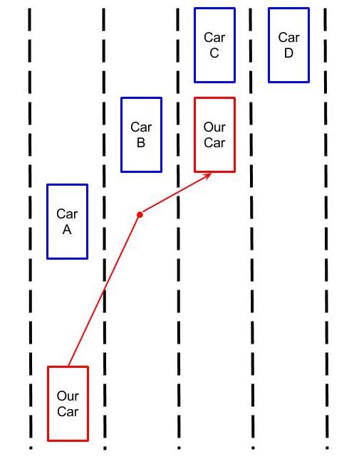
In our design, the car is running on a three-lane highway. We used three ultrasonic sensors to detect the distance of front, left and right in order to make corresponding reaction. Two infrared sensor were attached on the bottom of the car in order to detect the lane mark so that it could perform merging and auto lane correction. If there is no car ahead, our car will just keep going straight. If there is a car in front of our car and the one of the lanes next to our car is clear, our car will switch to that lane. If there’s car in front of it and two side lanes are blocked, it will stop until the front blocking car is moving ahead. If there’s no car around and our car is accidentally driving out of the current lane, it will automatically correct itself into the original lane. The figures below shows an example route of our car on the highway and our finished car.

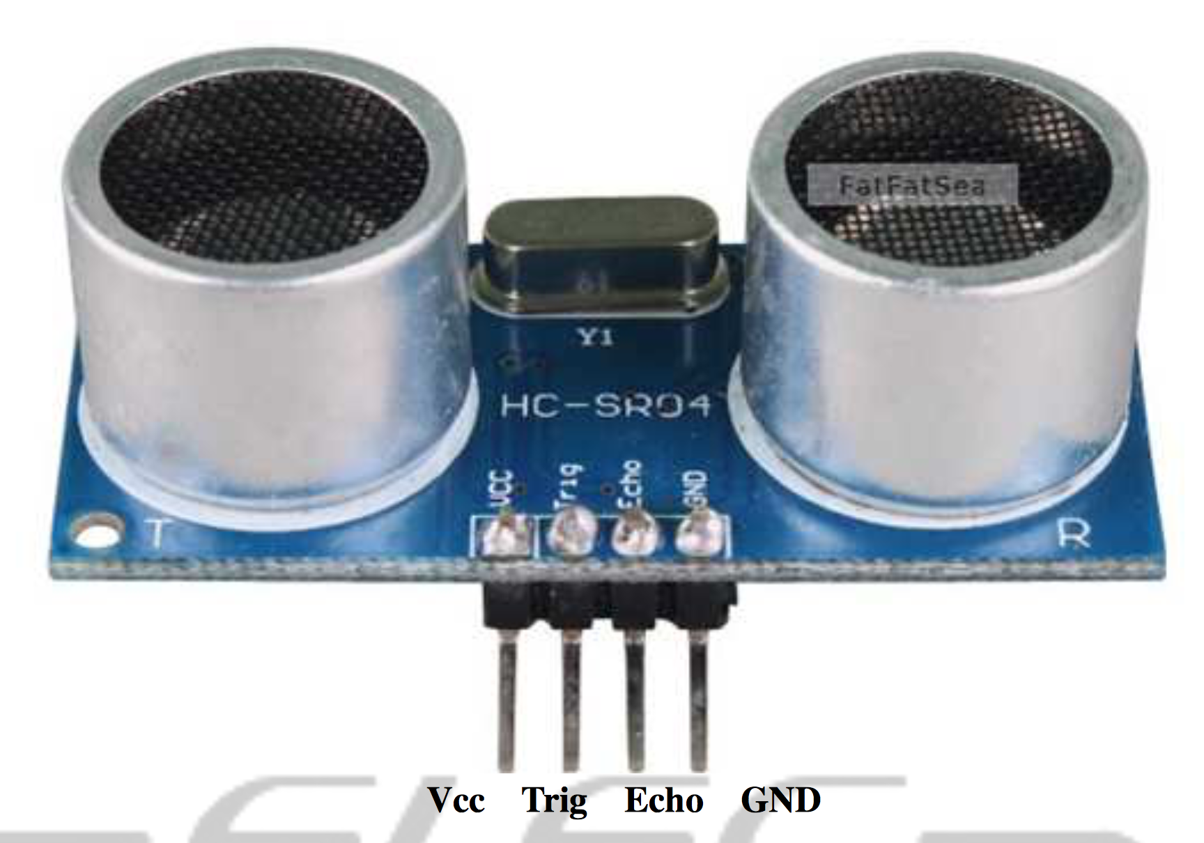
We first reassembled the car used in lab 3 and the ultrasonic distance sensors we bought arrived. After finishing the reassemble of the car, we tested the ultrasonic distance sensor with a python program. The ultrasonic distance sensor we used is hc-sr04 and the figure below shows the sensor. The working voltage of this sensor is 5V and the proposed minimum detection distance is 2cm, but based on our testing, the minimum distance it could detected is 13cm (not steady) or 15 cm (steady) [1]. We used a Python library called gpiozero and implemented a DistanceSensor instance for each sensor. The distance is returned in centimeter and the testing code is attached in the code appendix section called sonar_test.py.

Once we finish the testing of the ultrasonic distance sensor, we developed a python program that makes the car go forward and stops the car when the sensor detects an obstacle within 30 cm. Since the original python program was keeping modified and finally developed into the final program that drives the car, there’s no code example shown in the code appendix session.
As the next step, we bought four infrared sensors for the purpose of lane detection and lane correction. The model we used is SMAKN TCRT5000. The infrared sensor is a reflective optical sensor. It has a operation voltage of 5V. The emitter wavelength is 950 nm and it has a feature of daylight blocking filter [2]. On the GPIO pin connection side, it also has a potentiometer for adjusting sensitivity, which is extremely useful. For example, the distance of detection would affect the detection result, but by adjusting the sensitivity, this problem could be solved.
We also tested the infrared sensor by writing a python program. The python code is called line_test.py and it could be found at the session of code appendix. The working principle is comparatively easy. When the GPIO.input==GPIO.HIGH, it indicates white; when it’s LOW, it indicates black. In line_test.py, we connected the left infrared sensor to GPIO pin 5 and right infrared sensor to GPIO pin 6. We created an infinity loop for detecting colors and kept printing on the screen to check for correctness. At very first we found that the sensor is strongly affected by the distance, but later we solve it by adjusting the sensitivity by turning the potentiometer on the GPIO connection end.
Next, we connected another two ultrasonic sensor by the side of the car for detecting if there are cars on the left and right. Since we need eight GPIO pins in total, we had to re-wiring, but the original board was not large enough for holding those wires and ports. We switched to a larger breadboard and redid the wiring to make it looks tidy.
After the assembly is finished, we implemented the lang changing algorithm. The python code is called auto_lane_changing.py and can be accessed at code appendix section. After developing the lane switching algorithm, we also tested it. Here are several main issues with our car:
1. The software pwm we use sometimes causes the car to wiggle when going straight.
2. The minimum detection distance of the ultrasonic sensor is limited, which further affects the accuracy of lane-switching function.
3. The material of the wheel causes the car to slip.
Next we added the feature of lane keeping, which also referrs to lane correction. The algorithm involves some geometry and basic physics, which is explained in the detailed comments in the code. After developing the lane keeping code, we also tested it and it runs perfectly. Despite some minor issues mentioned above, the car now performs stable lane changing and lane keeping.
Video
Below is a video of the demonstration of our robot.
Results
Based on our testing and demo, every function could work but not that perfect, especially for the lane switching. Due to the material of the wheel and the power balancing failure of the servo, sometimes the car could not go straight, which will cause the false detection of the ultrasonic sensor and then affected the corresponding lane-switching function. For the lane-keeping function, it works perfectly. Basically, our design met the goal outlined in the description.
Conclusion
In conclusion, our project is successful. Our design meets the original goal when proposed the project. For the design process, each function and sensor was designed and tested separately, then integrated together. In time consequence, we firstly tested the ultrasonic sensor, then the infrared sensor. After figuring out how those sensor works, we started building the lane-switching logic and applied that onto our car model consisted with R-pi, ultrasonic sensor, infrared sensor and servo. Finally, we designed, implemented and integrated the lane-keeping function onto the existing car model.
Future Work
The main proposed future work is focusing on the car model itself instead of the logic. Basically, here are several things could be improved. Firstly, we want to re-wiring all the components onto a smaller customized breadboard, so that the minimum detection distance limitation of ultrasonic sensor on the two side could be reduced. Secondary, if possible, the wheels driven by the servo could be made with better material with high friction. Thirdly, another two sensors are proposed to be installed in the front for the purpose of improving front detection accuracy.
Budget
1. Four hc-sr04 sensors: $19.98
2. Infrared line follower module: $10.99
Total: $30.97
Code Appendix
References
[1] Support:, Tech. Ultrasonic Ranging Module HC - SR04 (n.d.): n. pag. Web. http://www.micropik.com/PDF/HCSR04.pdf
[2] Semiconductors, Vishay. TCRT5000, TCRT5000L (n.d.): n. pag. Web. http://www.vishay.com/docs/83760/tcrt5000.pdf
Contact
Team Members:
Tianfang Liu tl697@cornell.edu
Liming Yang ly337@cornell.edu
Project Advisor:
Joe Skovira jfs9@cornell.edu