Design and Testing
Dashcam
For our dashcam, we used the Raspberry Pi Camera Module V2 found here on Amazon. We chose this camera because it was easy to hook up to the Raspberry Pi, had native support, great resolution and was well supported with a lot of online resources.
We started by setting up the pi parameters and taking test shots at different resolutions and modes. We chose to use the record mode while grabbing frames from the video_port (which is faster because we’re already recording) to the python module. We then did this while implementing multiprocessing so the pi could use all 4 cores. This was done with the multiprocessing library by creating a pool of 4 processors where each process would pick from the pool to run its process and the pi would automatically schedule the process to an appropriate and free core.
We continued by testing different resolutions and figuring out what the optimal FPS to Resolution trade-off would be. We ended up at a 480 x 360 resolution because we were getting 10fps of processing (and 17fps while grabbing frames from the videoport). These were all done using all 4 cores. Note that the recorded video itself is at 30fps but the pi cannot grab more than 17 frames per second to do image processing on.
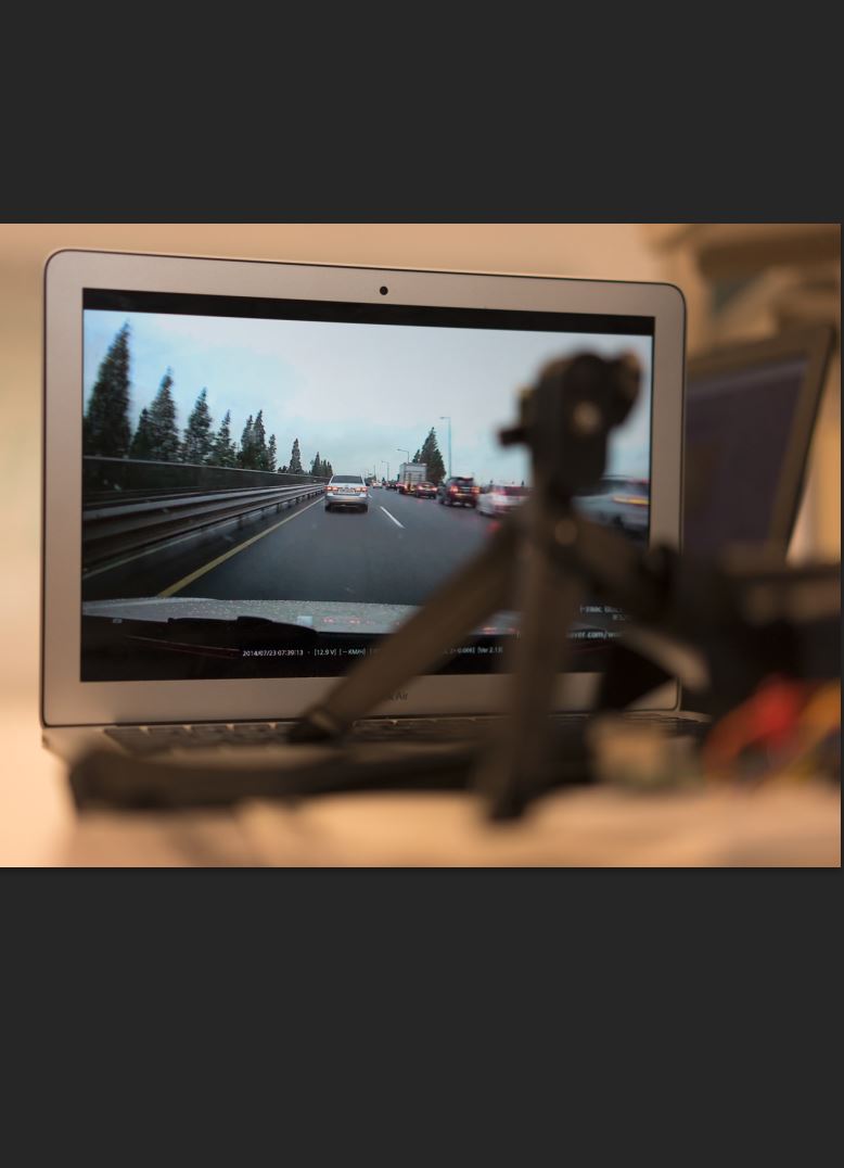
The dashcam itself also recorded at 480x360 pixels. The feed from the camera would be written to the flash drive. We made the length of each clip variable in number of seconds. This is because we wanted to prevent as much data loss while recording as possible for example, in the event of a quick shutdown, we wouldn’t want 30min of recording to be corrupted. We named the videos by the date to make it easy to be found.
To ensure that video could be continuously saved to the external drive, we created a script that would check the percentage of the drive that was full. If the percentage exceeded a certain threshold (we used 90%), then the script would automatically delete the oldest footage. This script works for external drives of any size, because it detects the percentage of the drive that is filled, rather than a hard-coded memory quantity. We ran this script on a timer within our main scripts. We found timers (in addition to the multiprocessing) module to be extremely helpful. It allowed us to sample the IMU fast enough to detect collisions quickly even when our main loop ran only 10 times a second.
Lane Departure Warning System
We used the openCV module to help us detect the lines. The steps are as follows,
- Crop the image appropriately to reduce unneeded processing.
- Change to Black and white because color information is unneeded (and since it uses 3 layers to store than information, we don’t want to calculate line detection for all layers.)
- Apply a layer of gaussian blur to smooth out noise. An example can be seen below of the effect of line detection with and without the blur added.
- We then run a Canny edge detection algorithm on our blurred image to detect the lines resulting in a binary MAT image with the edges being white.
- We finally run a hough probabilistic line detection on the canny edge image. This will try to find the most likely lines. We then draw the lines on the image using the cv2 lines function.
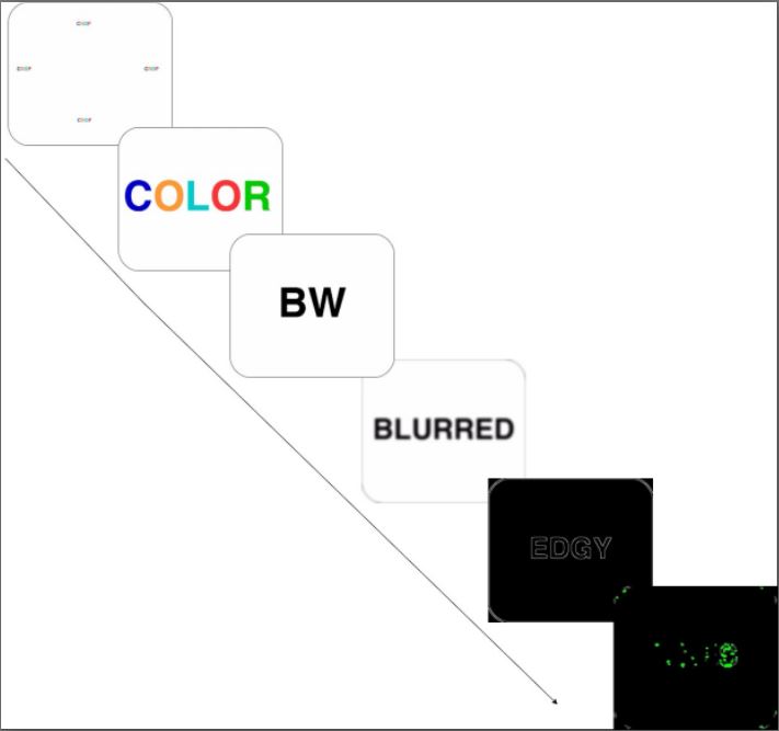
Steps to line detection
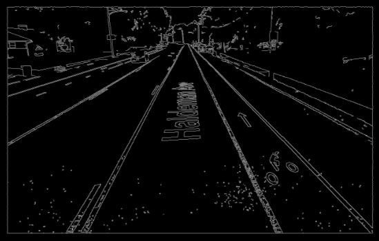
Edge Detection without Blurring first
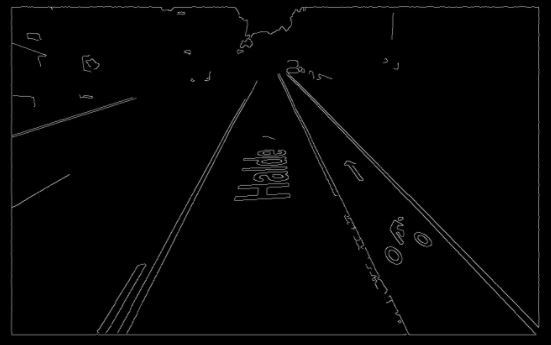
Edge Detection after Gaussian Blur applied
The hough line detection algorithm will detect many lines on the image. To ensure that only lane markers are detected, we crop out the top 80% of the image and only perform line detection on the bottom 20%.
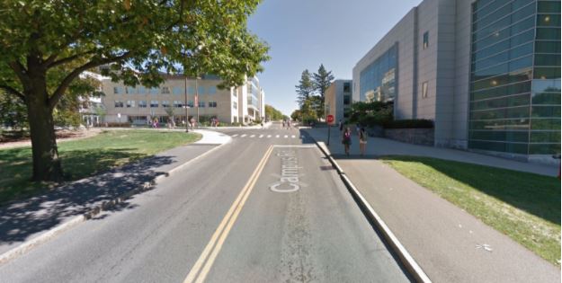
Before Crop and Lane detection

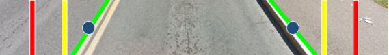
After Crop and Lane detection
We iterate through the set of lines found in the image and pick out the longest line with a positive slope, and the longest line with a negative slope. These correspond to lines representing the right and left lane markers respectively. The left and right lane marker lines may not extend to the top and bottom of the image, so we do some simple math to extend them into the green lines seen in the above image. Using these lane markers, we came up with 3 different ways to detect whether a car was drifting out of its lane.
- Set static thresholds at certain points of the image. Find the midpoint of the two lines, and detect whether either of those two points leave the bounds of the thresholds. The two images below show examples of when the vehicle is within lane bounds, and when the vehicle is drifting. Note that in both images below, the yellow and red threshold lines remain in the same position. In the bottom image, the vehicle is drifting to the left.
Vehicle is within lane bounds
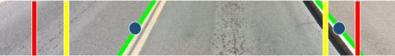
Vehicle drifting slightly. Yellow warning light would turn on.
- Again, use two boundaries for the yellow warning and red danger signals. This time, we take the lower endpoints of the lane markers and compute the midpoint. We detect whether the midpoint leaves the bounds set by the thresholds.
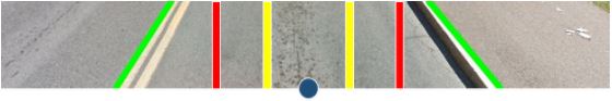
Vehicle is within lane bounds

Vehicle drifting slightly
- Take the upper endpoints of the lane markers and compute the midpoint. Take the lower endpoints of the lane markers and compute the midpoints. Then, find the slope of the line traveling through the midpoints. Ensure that the absolute value of the slope does not exceed the threshold slopes. In the image below, the blue line represents the line connecting the two midpoints. The yellow and red lines represent the slope thresholds that the blue line should not cross.
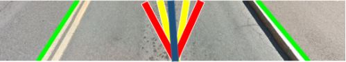
Vehicle is within lane bounds
Accelerometer/Compass
We used a UCTRONICS MPU-9255 9-Axis Sensor Module found here on Amazon. We used the I2C protocol, which allowed for communication with the device using just 4 wires: VCC, GND, SCL, and SDA.
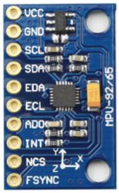
IMU Used
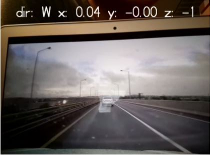
First, we used an online guide found at bitify to obtain data from the IMU. This guide allowed us to get accelerometer and gyro data by reading directly from the memory addresses on the IMU. The code for this process was difficult to read and understand, so we switched to using a modified version of the RTIMULib2 library found here. This library allowed us to obtain data from the IMU chip with abstracted function calls and custom calibration settings. During testing, we were able to obtain data at a rate of 250 samples per second. The accelerometer arrived in raw, unitless values, so we had to find a mapping from these values to G-forces. We did this by downloading an app on our phones that used the smartphone’s accelerometers to compute G-forces. By physically attaching the phone to the IMU, we were able to see which values from the IMU corresponded to the G-forces being detected by the phone. The IMU also provided magnetometer data, which we used to figure out the cardinal direction that a vehicle is facing. We used a compass to help us translate the x and y direction magnetometer readings into cardinal directions.
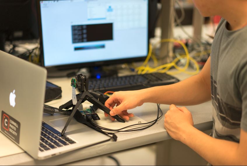
Integration of components
We set up a testing mode where our script would take arguments and behave accordingly. This is what we used to shape the algorithm. The testing mode for example would read in a ‘test.jpg’ and apply our functions to it and show us the results.We did this before testing any moving roads. This helped make integration easier as we could switch off and on functions we wanted to test.
Our dashcam integrated nicely with the lane detection because they were able to run concurrently without any problems. The IMU in the other hand needed a bit of repeated polling which we accomplished using the Timer library on the raspberry pi. We had it run a function to poll the IMU unit every 5 milliseconds(or 200 times a second). This meant we could detect impending accidents much faster than the 9-10 fps we had our main loop running at.
We also used a timer for the memory sweeping operation to clear out disk space after 90% usage