Near Space Time Lapse and Radio Frequency Based Telemetry
Ronald Forster (rjf257) and Alexa Ditonto (ajd245)
Objective
Near space photography is the practice of obtaining photos within the upper atmosphere so that images of the Earth’s surface and Horizon can be acquired from a very different perspective than surface photography. In order to do that, a system must be created that can rise to the upper atmosphere while simultaneously capturing these images and reporting the location of the embedded system. The simplest way to do this is to create an untethered system lifted by a weather balloon that utilizes radio frequencies to automatically send packets to a ground station network detailing the systems location as measured with a GPS attachment. Using this system, pictures and position packets can be sent at variable times so the system can be successfully retrieved after landing.
Introduction
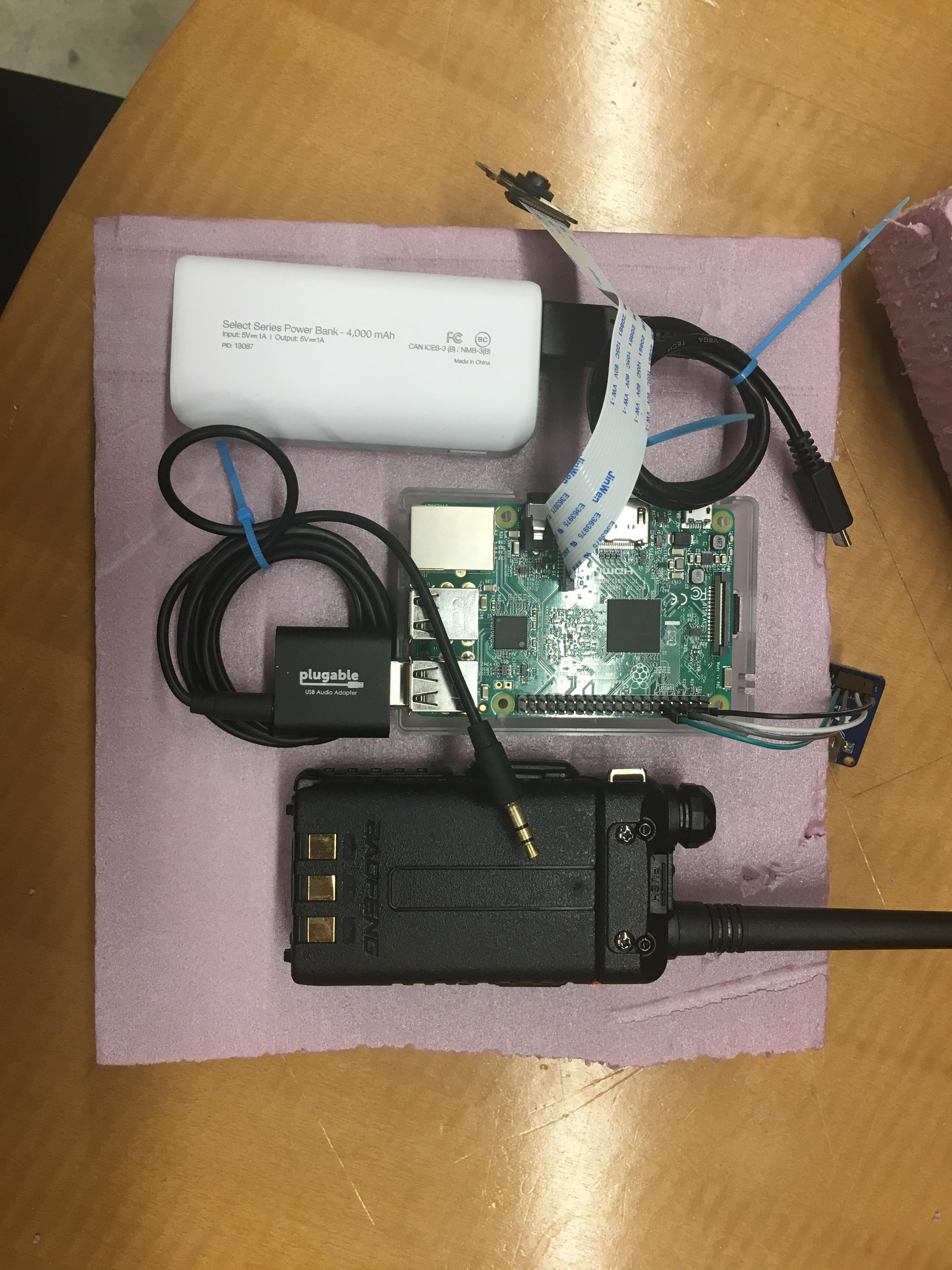
This solution for the objective given above utilized a Raspberry Pi as the main embedded system that was coupled with a Raspberry Pi camera for pictures, an Adafruit Ultimate GPS Breakout for position acquisition, a Baofeng UV-5R Transceiver for position packet transmission, and an external battery for power. On the Raspberry Pi, a program called Direwolf was used to convert the GPS output into audio APRS signals for transmission by the Transceiver. Additionally a custom python code was created to command the Raspberry Pi camera to capture images and save them, a custom bash script was created to start the image capture python code and direwolf program simultaneously, and a custom initialization bash was created to configure the Pi for proper inputs/outputs and begin the data collection programs within the rc.local startup script. Finally a casing was created using foam in order to contain all electrical components. This casing was attached to a custom parachute and a weather balloon for ascent to the upper atmosphere and descent back to ground.
Video Presentation
https://www.youtube.com/watch?v=tgkQ97itWV4
Design and Testing
The initial step in the design process for this system was to research other similar systems that have successfully travelled to near space. Multiple systems completed similar things such as (http://makezine.com/projects/near-space-balloon-cam-with-arduino-and-aprs-radio/) a project by Dan Rasmussen on Makezine or a site that shows many completed launches by John Flaig called Near Space Ballooning (http://www.nearspaceballooning.com/) but there were a couple of restrictions on our flight led to us using a slightly different method tailored to our needs and our experience. Due to restrictions of the class, the Raspberry Pi had to be central to our embedded system since it was one of the main devices used throughout the class. For this reason Dan Rasmussen’s setup wasn’t quite right since it used an Arduino. Additionally our setup was limited to $100 for the project, meaning that many of the setups used on “Near Space Ballooning” were not realistic since they utilized more expensive equipment. In our approach we decided to use a conglomeration of the different techniques that we found online in order to complete the project. With the help of a Cornell Staff member named Michael Hojnowski, we were able to shape that idea into reality for a balloon launch.
The basic design of the system can be broken down into 6 components: GPS, Computer, Battery, Transmitter, Camera, and Container. When researching parts for each of the different components of our system, a couple of roadblocks were quickly hit. The computer component was easy to define since it was required to be a Raspberry Pi by the project definition. The rest of the components we had to define ourselves.
Our initial thought for a GPS module was the Adafruit Ultimate GPS Breakout. Unfortunately, this breakout is quite popular due to the capabilities it has and the cheap price it goes for. Fortunately adafruit sold a similar Ultimate GPS HAT but it was more expensive than the breakout and limited the modularity in our mechanical design since it was restricted to be mounted on the Pi itself. Since we were looking for the cheapest things possible and weren’t completely sure what our mechanical design would look like, we wanted the breakout more. Luckily some came in stock right as we were about to order parts for our system but if the breakout wouldn’t have been available, the HAT would’ve been an equally viable option. The Ultimate Breakout was setup using Adafruit’s guides (https://learn.adafruit.com/adafruit-ultimate-gps-on-the-raspberry-pi/setting-everything-up?view=all) in order to utilize UART to send GPS signals to a GPS daemon on the Raspberry Pi using the TX and RX pins on the Raspberry Pi Breakout (Pin 8 for TX and Pin 10 for RX). Since we wanted the GPS to be properly configured on each setup, the code for setting up the the UART GPS input on a Raspberry Pi 3 was included in the rc.local script using a bash so the GPS would be setup on startup.
From the research on similar near space projects, it was clear that in order to transmit our data we would have to operate a transmitter on an amateur radio frequency. This came with two problems. The first problem stemmed from the requirement that anyone who wanted to transmit on these frequencies had to be certified for a Technician’s License for Radio through the FCC. This meant that one of the group members had to pass the Technician’s License exam. Luckily the ARRL has many practice materials that make learning and studying for the exam easy. These materials can be found on their website (http://www.arrl.org/exam-practice). The second large barrier we had to pass was finding a transmitter that was able to transmit on the amateur radio frequency of 144.39 MHz. Although the frequency band is very popular since it is essentially the beginner’s band, we were only able to find one transmitter within our price range and it was only sold at a reasonable price in a foreign country, which meant the lead time for shipping was out of our scope. After meeting with Mike Hojnowski, he showed us that a better way to transmit for projects like these on a budget was to buy a simple transciever that could be controlled to transmit the signals at whatever frequency the user desired. The downside to using this mehtod is that the transciever is operated usually through Push To Talk which means that a user would have to hold down a button to transmit or would have to use a manually built circuit to activate transmission. After some research, we were able to find a compromise with transceivers that have VOX or Voice Operated Control. This would allow our system to send signals with aux that would activate the transceivers transmission simply by being sent to the transceiver. This project utilized the Baofeng UV-5R since it is cheap, can operate off of VOX, and can transmit at our desired frequency.
The next big challenge was figuring out how to take the data from the GPS and sending it to the transceiver. Since the GPS operated off the GPIO pins on the Raspberry Pi and the transceiver took an aux signal in, the Raspberry Pi had to take this information from it’s GPIO pins and output somehow an aux signal. A majority of similar projects use the APRS or Automatic Packet Reporting System in order to transmit something’s location over the radio frequencies. For the Raspberry Pi, there were a couple of options for completing this GPS to APRS packet translation but this project decided to utilize Direwolf due to existing documentation on GPS tracking systems. Direwolf takes a simple configuration file as user specified input and is able to automatically create packets given a GPS input using the GPSD on the Pi that was setup with the GPS breakout. The biggest problem at this point was figuring out where the output from the Direwolf program would be sent to in order to be relaying to an aux signal for the transceiver. As per Mike Hojnowski’s recommendation, USB would be the easier interface for sending signals, the USB to aux soundcard became the selection for the project since a simple aux cord could be plugged into the soundcard and the sound card could be plugged into the Raspberry Pi. In order to install Direwolf, Section 5 of the User Guide on the website (https://github.com/wb2osz/direwolf/blob/master/doc/User-Guide.pdf) was used. After that, the output to USB was set using section 9.1.3 of the same user guide. Finally, in order to set up the configuration file, the provided documentation (https://github.com/wb2osz/direwolf/blob/master/doc/Raspberry-Pi-APRS-Tracker.pdf) was utilized starting at step 5 with a slight edit to the TBEACON code to include “balloon” instead of the call to car and the transmission EVERY=1 to transmit every minute.
The next important aspect of the design was the image collection. The Raspberry Pi, which is central to our project, comes with a Raspberry Pi camera from Adafruit (https://www.adafruit.com/product/3099) that is simple enough to use and nice enough to get somewhat quality images and is still cheap. The camera plugs directly into the Raspberry Pi and can easily be controlled through Python code. By creating a simple code found in the code appendix, the system was able to be commanded to take pictures every 20 seconds. This worked by utilizing a while loop to control the overall amount of pictures to take, the internal time from the Raspberry Pi, and a time checker that would collect an image from the Raspberry Pi and save it on the desktop at each commanded interval.
Finally, in order to power the entire system a power analysis was completed of the theoretical system in order to figure out the power consumption of all parts. Since the transceiver is an enclosed and individual unit with its own battery, no extra power was needed. Additionally since the GPS operates off the Raspberry Pi’s power, then the calculation for power consumption can come down to the needs of a loaded Raspberry Pi that is completing commands and powering external attachments. Using the website (https://www.pidramble.com/wiki/benchmarks/power-consumption) which contains data about Raspberry Pi power usage and the knowledge that many batteries are specified using mAh (of milliamp-hours), then the total battery size can be known by multiplying the Raspberry Pi Power use by the time of operation of the system. Since our system would take approximately 2 hours according to trajectory trackers such as this (http://predict.habhub.org/) and according to the power consumption measurements a reasonable Pi power consumption for our project would be 500 mA, then we would need 1000 mAh of power. We decided to go larger than necessary in order to make sure the system can operate before and after the flight, extend retrieval time, and allow a Factor of Safety for error. The original solution was to use a battery pack filled with AA batteries but this would require potentially problematic input connections to the GPIO pins on the Raspberry Pi. Additionally, this amount of power is easily found in most external batteries, which can easily connect to the raspberry Pi thanks to USB to 5 V connectors.
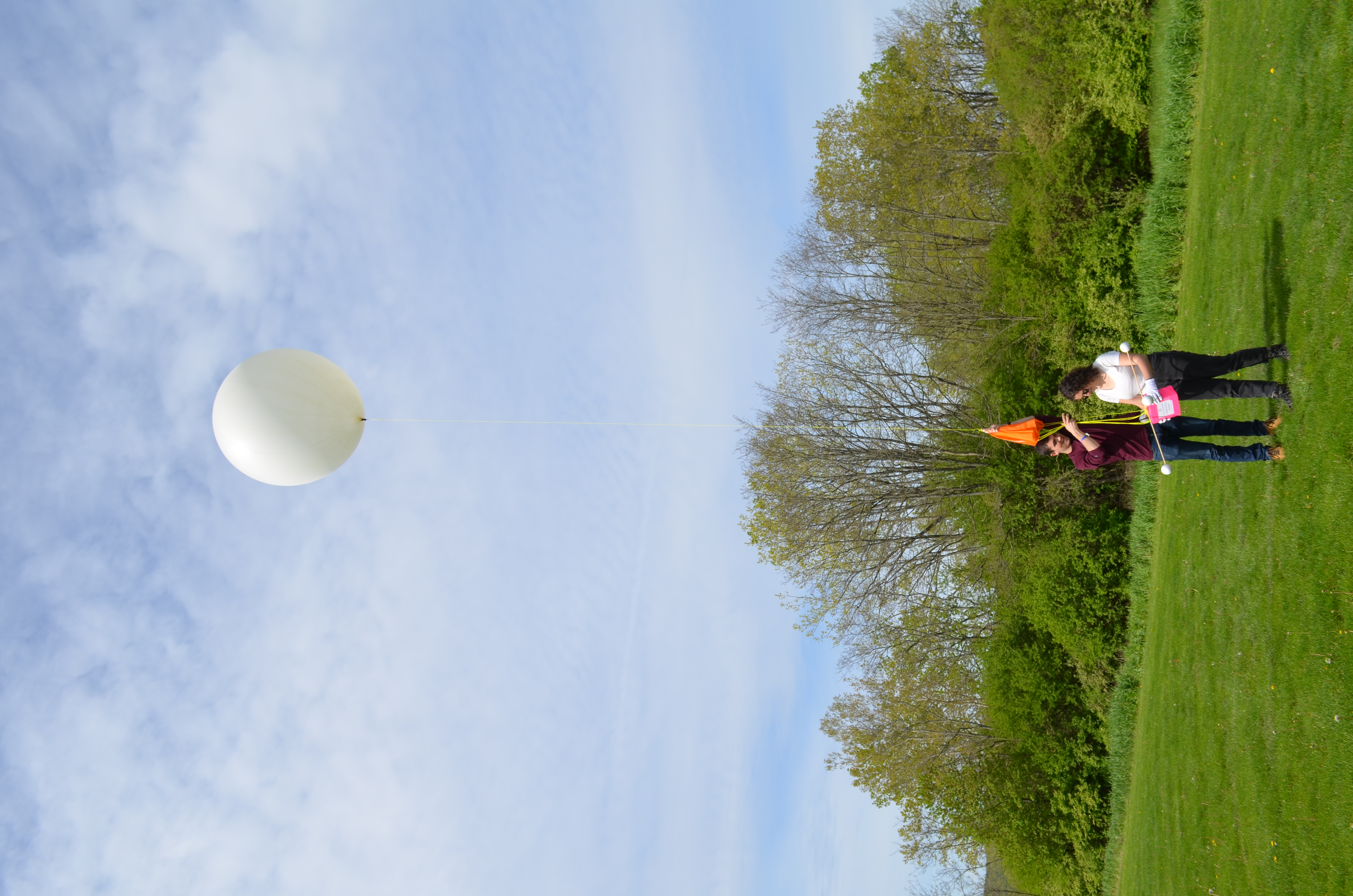
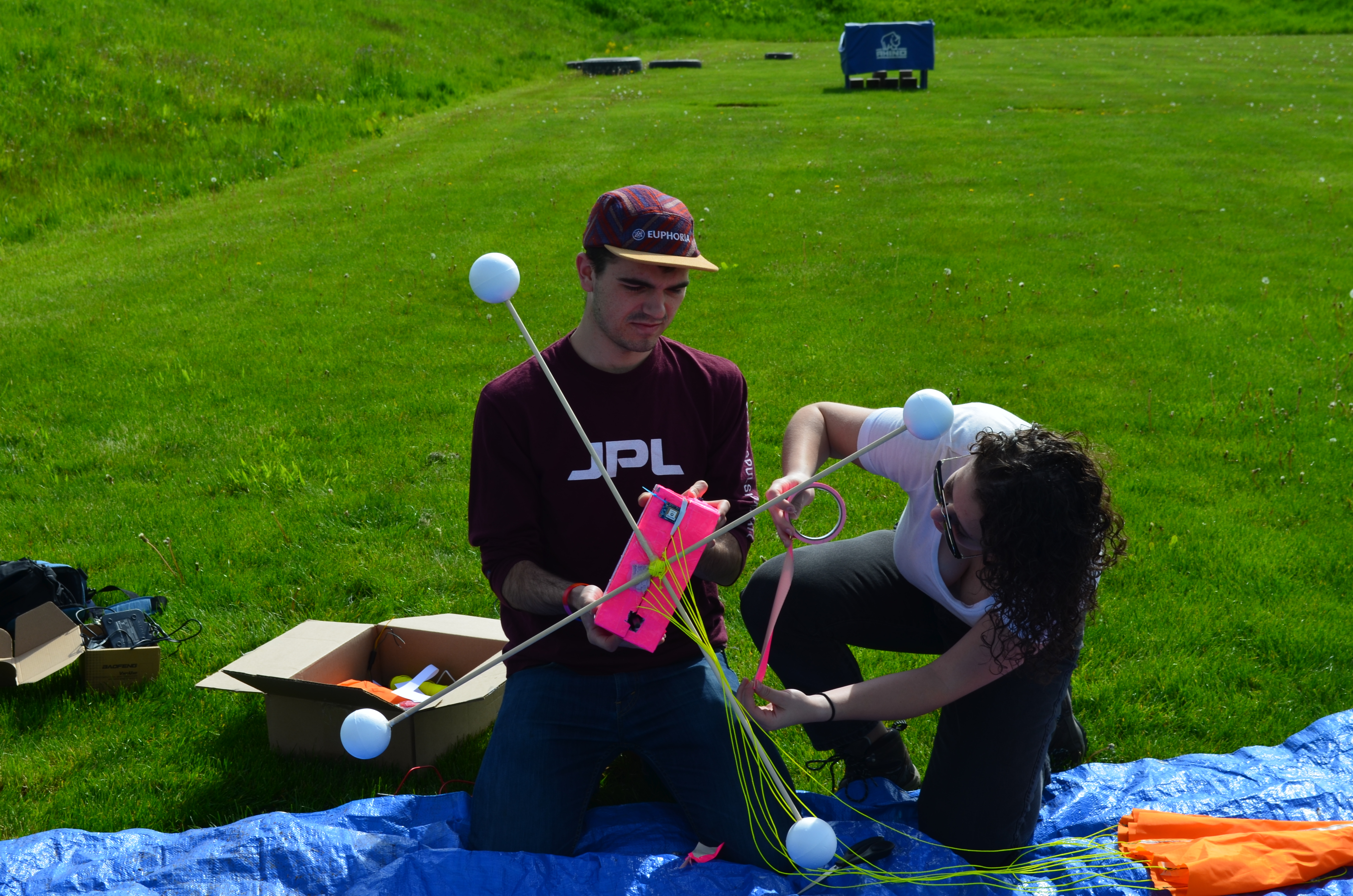
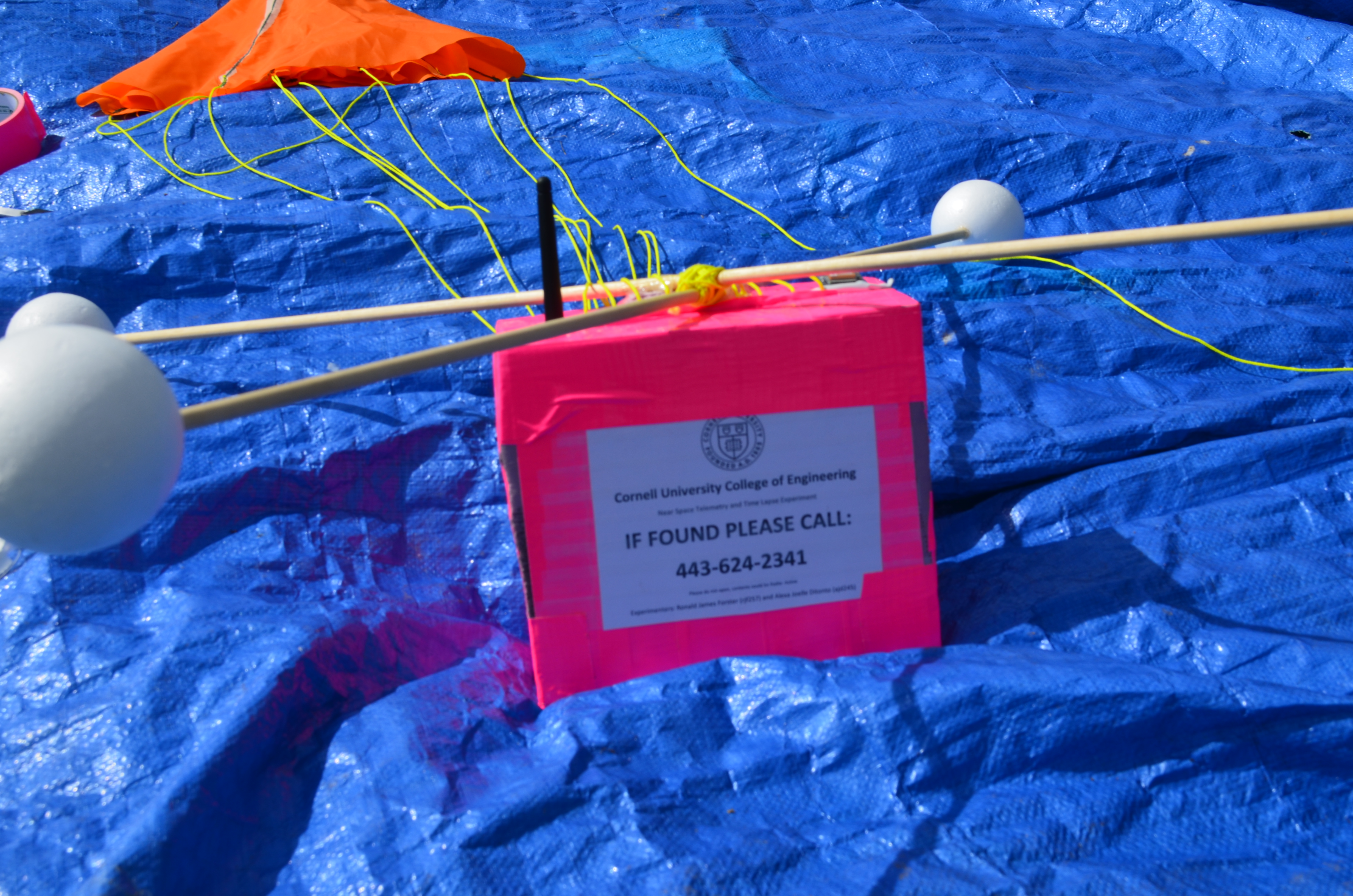
Finally, the last component of the system was the casing and mechanical parts that would carry the electronic embedded system to space. In order to lift the system, a 300 g weather balloon was chosen since it was the smallest and cheapest of its kind and would mean a shorter flight which also means a higher chance of retrieving the system. This weather balloon was attached to a parachute that was hand sewn in a hexagonal formation using Rip-Stop Nylon. The parachute then attached to a custom foam encasement that housed all electronics and mounted the camera, gps module, and transceiver antennae on the outside of the system.
Finally, the two codes that were required to run in order to create the fully functional system (Direwolf and our python code for the time lapse) were combined in a bash script that calls both codes in as background processes. This bash script would be called on startup to initialize our system.
In order to prove that our system worked, multiple tests were performed throughout the design and fabrication process. The three main testing areas were transmission and receiving of GPS packets, image capture, and mechanical design.
Transmission testing began with setting up the GPS and figuring out how to obtain a fix using the function cgps to display the output of the gps. Through testing it was determined that the GPS would not fix immediately, taking anywhere from a minute to ten minutes to fix. Additionally, we discovered that although windows seem to provide a “straight line of view” to satellites necessary to give the GPS a fix, many windows will not allow the necessary signals through and therefore the GPS would not be able to fix. Next was configuring and testing Direwolf to make sure it was able to create packets using the fixed GPS signal. This was completed by simply calling the Direwolf function after altering the configuration file and making sure that Direwolf would output pink lines of APRS packets. The main problem discovered in this portion of the testing was that some of the Direwolf configuration given in the cited guide did not match our desired output. These changes are detailed in the paragraph above on Direwolf. Once the packets were officially reporting, the transceiver was connected to the Pi using the USB soundcard and put into its VOX mode. Dring this testing, the different cutoffs of VOX triggers were tested in order to make sure the VOX would only be activated by the aux input and not other noises. During this testing, we also ran into problems because of a hand soldered aux cord which was soldered incorrectly. This ended up damaging the soundcard, leading to the eventual replacement of a sound card. Transmissions were validated using a second Baofeng transceiver and eventually through outdoor testing to make sure nearby stations could pick up the signal. Using the website aprs.fi, we were able to validate that our packets were picked up by the HAM radio network by searching for our call sign to pop up on the map (check out KD2NMA-11 for proof).
Camera testing was completed in lab by simply taking multiple pictures at given times and opening them up later to confirm proper capture. Similarly, mechanical testing was done at various points through the fabrication, such as strength testing of the parachute and box through violent motions and drops as well as force testing each of the mechanical connections such as between the parachute and the system. Once all parts of the system were properly configured, assembly and integration testing occurred in order to make sure that the entire system was functional and assemblable.
The final testing occurred the day of launch after the final assembly occured by making sure that the system was properly transmitting and was being picked up by nearby stations. Once all systems were checked, the balloon was inflated and launched into the sky.
Results
The entire system was created as planned as seen in the in-lab demo, with minor deviations such as the lack of altitude measurements within the packets that were reported for the localization of the system which wasn’t required for proper system functionality. The system was able to report its location to nearby stations so that its current position was able to be updated online. Additionally images were able to be taken at user specified times, meaning the system had all capabilities for the required telemetry and time lapse capture. Although initial launch and tracking work perfectly, the gps unfortunately ended up giving out halfway through the balloons trajectory to the upper atmosphere most likely due to the temperature differences due to the lack of air in the upper atmosphere.
Since the system was unable to obtain updated measurements of its location, it continuously beaconed the same localization information which was nowhere near its actual location. We knew the system had failed at the gps level because the final position reported by the system also reported a velocity of 80 mph. Since multiple packets reported this position all with a velocity of 80 mph and a system travelling at 80 mph should change positions between each beacon, all aspects of the system (Including the Raspberry Pi Direwolf translator and the Transceivers intermittent transmissions) were working except for the actual GPS measurement. This problem was most likely cause by the fact that the GPS was one of only two parts of the system exposed to the environment. Both the GPS and the Raspberry Pi camera were mounted to the outside of the container and therefore were exposed to the elements whereas the battery, raspberry pi, and transceiver were all protected within the foam. This meant that the exposed elements were less able to retain heat and probably froze leading to malfunction whereas the contained elements kept their heat thanks to the protection of the foam. In order to solve this problem, the gps could be contained inside the foam instead of outside of the foam, which will reduce its localization abilities possibly causing errors in its ability to fix its location but will make sure the system can continue to work and doesn’t freeze.
Conclusion
The biggest takeaway that came from this trial run is that although we had complete many analyses and tested our system before launching, there are still many things that can go wrong with any near space experiment due to the unpredictability of nature. Although we had anticipated some problems with the temperature differences between the ground and the upper atmosphere, we thought that those problems would only occur with the main electronics and wouldn’t extend to the GPS breakout. Additionally, since we are unable to retrieve the device to ascertain the exact error, we do not actually know what occurred during the flight that led to the fatal error. For this reason, we believe that for future flights we should always have a backup system that has been confirmed to work onboard in case something goes wrong that way the unit can still be retrieved to discover and remedy the error. Many schools and areas have HAM radio clubs and many of these clubs have done similar balloon launches and will most likely be able to double check a system and offer a backup. For that reason, the group is currently planning on launching another balloon with a backup tracker provided by Mike Hojnowski in order to hopefully complete a successful flight.
Other conclusions that were found through the experiment were that Direwolf, although a fantastic program, is very well documented for some things but not well documented for users that plan to stray from the given and documented applications. One of the main times this came up was while attempting to alter the telemetry signal that was being sent to the stations so we could locate the system. Although the TBEACON command given was able to provide some information, it was very difficult to find any documentation on coding in different outputs than was simply given by the TBEACON command. Additionally, we learned to not underestimate the amount of time that goes into the mechanical portion of building the encasement to the system and attaching all required parachutes, mounts, etc..
Future Work
Since one of the biggest obstacles that was traversed during the testing and operation of the system was the reception of the system in regards to the GPS’s ability to fix its location and the transceivers ability to transmit packets to nearby stations, it would be beneficial to look into reception enhanced devices or antennas to improve the performance of the system. Although the system was able to perform as desired, many times the GPS would struggle to obtain a fix due to the lack of an external antennae and therefore weakened ability to pick up signals. On a similar note, the radio was only able to transmit to stations if a direct line of site was present, therefore if a building or obstacle was in the way the position transmissions wouldn’t be picked up.
Another interesting area to explore for the project would be the containment method of the system. Since the main failure of the system was the lack of protection of one of the electrical components due to the desire to improve connection capabilities, it is quite obvious that the protective capabilities were not adequate for our system. Although the GPS should theoretically work fine within the foam enclosure, the internal containment of the GPS still requires testing to ensure proper function. Additionally, if reception enhancing devices such as antennas are used, then the GPS would be able to easily be contained and protected with only the reception enhancing devices (which are more tolerant of extreme temperatures) exposed.
Finally looking into ways to add redundancy to the system would be beneficial due to the high chance of error in any near space experiment. Adding a second method of tracking the system and backups for power, transmission, and data capture would be extremely helpful in the chance of device failure like what was experienced in this situation.
Once a successful system has been tested and evaluated through a successful flight, adding a better camera would make the goal images look much better with more vivid images in order to catch the details that were most likely missed with the Raspberry Pi camera (such as the border of the atmosphere and space which can be seen with a nice enough camera and a higher altitude. On that note, doing a launch with a larger balloon will be able to get even cooler images since the curvature of the Earth will become more apparent and the blackness of space will become more spectacular.
Code Appendix
Full Code Bash Script
#!/bin/bash

python camera.py &
direwolf
|
Camera Python Script
from picamera import PiCamera
from time import sleep
from os import system

camera = PiCamera()
camera.start_preview()
for i in range(5):
	sleep(1)
	print('image{0:04d}.jpg'.format(i))
	camera.capture('image{0:04d}.jpg'.format(i))
camera.stop_preview()
system('convert -delay 10 -loop 0 image*.jpg animation.gif')
print('done')
|
Above, direwolf is a program too long to list here but can be found on Github.
Parts List
Ronnie’s contribution to the project was mainly in the localization and transmission of data as well as the overall function of the system. In order to make sure that our system could find itself and send that data to us, I configured and tested the GPS module and the transmitted and coded/tested the connection between the two devices. Additionally I complete battery life tests to make sure our system would be able to survive the entirety of the flight given the battery that was selected based off of my power analysis of the system. Finally I created the code that ran at startup to configure the Pi for all given functionality and run the operation code to begin data collection.
Alexa’s contribution to the project included pi camera and timelapse code and testing in order to capture an image every specified interval of time and stitch them together into a gif upon completion. I also hand sewed the parachute, designed and carved the internal layout of the foam container to fit all of the components snuggly and securely in the least possible amount of space. Finally, I set up the radio to phone and online tracking communication in order to track the payload within close range without internet connection.
We both contributed to selecting and ordering all of the necessary parts for this project. We also designed both electrical and mechanical systems together. We both studied for and obtained our radio licenses as well as general trajectory planning and launch day selection. We both fully supported launch execution and balloon tracking and chasing.
Parts List
Below is a parts list with prices summed seperately depending on whether the part was vital to the project or integral to the flight test setup.
| Part | Distributer | Quantity | Price | Project | Flight |
|---|---|---|---|---|---|
| Raspberry Pi 3B | N/A | 1 | 0 | 1 | 0 |
| Ultimate GPS Breakout | Adafruit | 1 | 40 | 1 | 0 |
| Baofeng Radio | Amazon | 1 | 25 | 1 | 1 |
| HAM Radio License | ARRL | 2 | 15 | 0 | 1 |
| External Battery | 1 | ||||
| Pi Camera | Adafruit | 1 | 25 | 1 | 0 |
| Balloon | Scientific Sales | 1 | 30 | 0 | 1 |
| Parachute | Joann Fabric's | 1 | 5 | 0 | 1 |
| Packaging | Joann Fabric's | 1 | 5 | 0 | 1 |
| Helium | Air Gas | 1 | 60 | 0 | 1 |
| 90 | 155 |