RPi Plant Watering Robot

Albert Quizon (aaq6@cornell.edu)
Srinivasan Seetharaman (ss3637@cornell.edu)
5/14/2017

Main Content

Abstract

A lot of homes have some form of plants, all of which need some sort of scheduled watering. A sprinkler or even drip irrigation system could work but would not be able to really handle a diverse set of plants. These systems are usually too expensive to implement around the house, and generally are more appropriate outdoors where stray water will be absorbed into the surrounding soil or ground.

The best way to water is to focus on the roots, not the leaves. Wetting the foliage results in a higher chance that diseases take ahold of the plant and cause problems. In addition, too much watering can be bad for the plants, so the frequency of watering would have to change based on the weather and sunlight.

We designed a robot to help with the collection of issues by watering specific targets at a designated time. The robot will monitor the soil for moisture levels and provide water then the moisture levels drop too low. It will be able to handle multiple plants which can be spread around the robot.

Main Content

Objective

The purpose of this robot is to monitor a collection of plants in a home setting. The robot will sample the moisture levels of the soil and when the level drops too low, it will pivot to the dry plant and water it. The robot finds each plant using color-based detection and centers itself on each tag. The robot arm will then lower and turn on the water pump to rehydrate the soil surrounding the plant.

Design

Color Recognition

The tag detection is a vital cog in our design which allows us to interface our bot with the moisture sensors. Using Open CV and RasPi Camera V2, we designed a robust tag recognition system based on colors (red, yellow and green) which are identified with particular sensors. When a sensor pings due to lack of moisture, the robot changes its findColor flag to the color associated with the appropriate sensor. In addition to detecting objects of a certain color, the recognition system also draws contours around the object and calculates the centroid of the object for use in the adjusting stage of our state machine.

Rotating Base

A centralized robot means either the robot rotates to target each plant, or the plants rotate to end up in front of the robot. Our design involves a rotating robot using two servo motors, a caster wheel, and a small dowel with a rubber stopper. The dowel and stopper keep the robot centered on a point and prevent drifting. The robot starts out viewing a red tag which it uses as a reference point. When a plant needs watering, the robot will pivot in place until it sees the appropriate color tag. It adjusts so that the color tag is centered in the field of view of the camera. The watering subsystem provides water at this point. When it finishes, the robot rotates back until it sees the red start tag.

Extending Arm and Pump

We needed to provide water from the centralized robot to each plant, so we designed an extended arm. This arm is long enough to keep the sprayed water away from the robot and to provide water to different sized plants. The arm will lower when watering plants and raise back up whenever it is not watering a plant. A pipe is attached along the arm so the water will be channeled in a specific direction. We use a 12V DC submersible water pump to push water  from the reservoir, through the piping, to the plant. The robot controls the activation of the water pump using a relay.

Moisture Sensors

In order to monitor the plants, we attached soil moisture sensors to the robot via long wires. While the wiring is not ideal and could cause tangling issues, this subsystem works well when dealing with 1-3 plants. Our code handles the change in moisture levels through callback functions. When a change in moisture level triggers a callback function, it checks if the output is high or low. If the output is low (moisture level is low), the robot will determine that the plant needs water. We implemented a queue of plants that need watering, so the plant/sensor ID is added to the queue.

Main Content

Hardware

Because of the budget constraint of $100, we used a lot of pre-built parts from other projects. We decided to build on a robot that was constructed for INFO 4410 Human Robot Interactions. The robot provided nice flat surfaces to build on and attach components to. The interior had enough space to house the Pi 3, breadboard, and the 12V battery pack required to power the water pump. The exterior walls were made of acrylic, which protected the interior electronics from stray water droplets. Two servos and a 5V battery pack had already been attached to the bottom of the robot, which we used to pivot the robot towards the different plants. The front panel of the robot already had a small hole drilled in it which served as a convenient means to wire the exterior electronics to the interior-located RPi3 and breadboard.

We originally had a problem with some drifting while turning on just the two servos and caster wheel. We determined that we could either build a track that would guide the wheels in a perfect circle, or attach a centralized pivot point. We tried building a rudimentary track out of balsa wood but it was hard to move around and sometimes caused the wheels to get stuck. In the end, we attached a dowel and rubber stopper to the bottom of the robot so it would pivot on a point. After some testing, it held up well and served its purpose.

The schematic of the circuitry was generally simple. We first wired in the moisture sensors to check the digital outputs to the RPi GPIOs. The sensor modules come with potentiometers which we adjusted. When the sensors were immersed in water, the digital output would be high. When removed from water, the sensors would output low. We connected extra cables between the sensors and the RPi 3 so tangling would be less of an issue.

In order to control the 12V water pump, we used a 5V relay. While it is a 5V relay, the 3.3V output from the RPi 3 digital write was enough to trigger the relay. The water pump and battery pack were wired to the Normally Open connection to the relay so that the water pump would only be powered when the relay input signal was high.

We used a RasPi Camera Module 2, attached via ribbon cable to the RPi. Finally, 3 servos were wired to the robot. We used an external 5V battery pack to power these servos, and attached current limiting resistors to the GPIO output pins. Two of the servos were attached to the bottom of the robot. They controlled the wheels to pivot the robot. One servo was placed at the top of the robot, used to lower and raise the extended lever arm.

Main Content

Software

The initial stages of software development began with moisture sensor testing. Once we confirmed the digital outputs, we created callback functions to handle changes in the moisture levels. This was a much more robust form of handling moisture sensor readings because they can interrupt the process at any point. In the callback functions, the triggered sensor ID was added to the needsWater queue, which lists the order in which plants are to be watered. A sensor will not be added to the queue is it is already in the queue. This is an implementation of FIFO, first in first out. The callback functions allow for sensors to be added to the queue even while the robot is in the process of watering another plant.

The next step was to test the different subsystems independently to ensure their functionality and test system requirements. We needed to make sure that the water pump was neither too weak nor too powerful. We wrote some test scripts that would toggle GPIO outputs in order to test the relay that controls the water pump.

We then tested the servo movements using previously developed pwm calibration code. Since we were using FS5103R continuous rotation servos without a built in potentiometer, we had to figure out the stopping pulse requirements. We then wrote functions that defined servo movement for quick reference when writing the finite state machine.

Callback Functions

# Green Sensor callback
def sensor1_callback(channel):
	if GPIO.input(channel):
		print "sensor1 on"
	else:
		print "sensor1 off"
		if("sensor1" not in needsWater):
			needsWater.append("sensor1")
			
# Red Sensor callback
def sensor2_callback(channel):
	if GPIO.input(channel):	
		print "sensor2 on"
	else:
		print "sensor2 off"
		if("sensor2" not in needsWater):
			needsWater.append("sensor2")
		

# Yellow Sensor callback
def sensor3_callback(channel):
	if GPIO.input(channel):
		print "sensor3 on"
	else:
		print "sensor3 off"
		if("sensor3" not in needsWater):
			needsWater.append("sensor3")

Color Recognition

	hsv = cv2.cvtColor(image, cv2.COLOR_BGR2HSV)
        mask = cv2.inRange(hsv, colorLB, colorUB)
        mask = cv2.erode(mask, None, iterations =2 )
        mask = cv2.dilate(mask, None , iterations =2 )

	# Ensure no stray element is detected as tag
	contours = cv2.findContours(mask.copy(), cv2.RETR_EXTERNAL, cv2.CHAIN_APPROX_SIMPLE)[-2]

        for c in contours:
                if cv2.contourArea(c) > pixel_size:

        ################# CENTROID OF THE TAG ##################
                        M = cv2.moments(c)
                        cx = int(M["m10"]/ M["m00"])
                        cy = int(M["m01"] / M["m00"])

			# Define contour and center
                        cv2.drawContours(image, [c] , -1, (0,255,255), 2 )
                        cv2.circle(image, (cx,cy), 7, (255,255,255), -1 )

	# Display on console for debugging
        #cv2.imshow("RAW", imageRaw)
        #cv2.imshow("Threshold", mask)
        #cv2.imshow("overlay", image)

The image processing technique involved the usage of openCV and PiCamera module on the RPi. We used the PiRGBArray to import RGB input from the picamera which is converted into a 2D array. The first step in this process is to convert the incoming RGB color schema into HSV color scheme. The reason why we decided to convert RGB to HSV color scheme is the simplicity in using HSV. It allows us to easily isolate the required color of the tag we are using through the use of simple hues. Hues are the bounded range for the color that we want identify.

We specified 3 tag colors: Red, Green and Yellow. We chose these 3 colors because we have the luxury of having a buffer in terms of color ranges. We defined the lower bound and the upper bound for the 3 colors through which we were able to recognize the above mentioned tags. We also defined a black color bounds for when the robot is in the waiting state and should not recognize any objects.

One of the biggest advantages converting from RGB to HSV is that HSV provides us with a more robust platform for detection. The hues are broad enough to cover the apparent colors, regardless of saturation or value. Next we perform a matrix operation on the pixel values that thresholds the colors to form a binary matrix of pixels which allows us to detect the colored tags. We reduce the noise from the resulting binary outputs using a morphological filter, which allows us to dilate the binary matrix. The filter provides us with a better output on which we can perform accurate contour detection. The output binary matrix obtained after dilation using the morphological filter maintains the edges and also fills up any values that have not been connected in the surrounding body.

We perform our contour detection using the Open CV library. The resulting binary matrix generated is used as the input for the contour detection function which provides us with a list of object boundaries. This list however does contain noise and elements which might interfere with our object detection. To prevent any erroneous detection, we filtered our contours out based on size. If the detected contour was smaller than a specified pixel area, it is not detected as an object. We also allowed our code to calculate the rough estimate of the centroid of the given tag. This was required because this allowed us to align our robot with the centroid. During our initial testing phase to help us with any underlying debugging issues, we overlaid the detected contour and shift into the raw RGB capture frame and displayed it to make sure we were capturing the required tag and not any stray elements.

Our final implementation of movement was a finite state machine. Our final state machine had 5 total states: Initialization, Left, Right, Adjusting, Watering, and Re-centering.

While in State 0, the robot sits in an initialization/waiting state. It keeps checking the queue. If the queue is empty, it keeps checking the queue. Depending on the sensor that first in the queue, the state then switches to either state 2, state 1, or state 4. If sensor 3 (Yellow tag) is first in the queue, the state switches to state 2, so it turns begins to turn left. If sensor 1 is first in the queue (Green tag), the state switches to state 1 and begins to turn right. If sensor 2 is first in the queue (Red tag), the robot does not move and skips straight to the watering plant stage since it should have already been centered on the red tag.

State 1/2 is a general movement stage. It constantly looks for the green/yellow tag until it shows up in the field of view. The initialization stage sets the findColor variable which is what color the robot looks for. When it detects an object of that color, it moves to state 3.

State 3 is the adjustment stage. Since we are dealing with water, the robot has to be particular when it decides to water the plant. We determined that we needed to move so that the colored tag would be centered in the field of view of the camera before watering the plant. The movements in this state are much smaller than in that of state 2 and 3, so the robot can adjust accurately. We determined that the robot would move to state 4 if the tag was within 5% (of the total field of view) of the horizontal center.

State 4 is the watering stage. The robot will then stop, lower the lever arm, and turn on the water pump to distribute about 1 seconds worth of water to the plant. The arm then raises back up so it does not remain in the field of view of the camera when it moves it again.

State 5 is the re-centering stage. The robot then turns left/right (through stage 2) back to the start point until it detects the red tag. It will then adjust (state 3) until it re-centers on red. The state changes to 0 and waits for a sensor to appear in the queue again.

Main Content

Testing

The first test was done on the callback functions for the sensors. We had to test to make sure that the appropriate sensor was being added to the needsWater queue when it was low on moisture.  The queue would not be updated if the activated sensor was already listed in the queue. This worked very smoothly as expected.

We then tested the tag recognition system. We were originally using a shape recognition system in order to maneuver to specific tags. That Open CV-based code was accurate at recognizing the different shapes when in an ideal all-white background. Unforunately, when testing the functionality of this system in a normal room, the code would only recognize circles robustly. Because of this issue, we determined that this would make the development of the finite state machine a lot more difficult. We decided to switch to the color recognition system.

In order to test our colored tag recognition system, we had to be considerate of three facets: color detection, discarding stray elements, and interfacing with the sensors. The first facet was to detect the color as accurately as possible while taking into consideration the lighting of the room, intensity of the light, and the color ranges. Keeping that in mind, we used HSV which provides us with more robustness. After defining the range of HSV colors in terms of upper bound and lower bound for each of the tag colors, we proceeded to test tag recognition by using the display function in cv2. We created an overlay window which allowed us to introduce a particular color that we were looking for, allowing for the display of contours and the approximate centroid of the image. The system identified the appropriate object, drew the contours around the object, and marked the centroid.

The next element was to make sure that no stray elements in the field of view was caught as a tag. The logical way to implement that was to set a minimum area for the tag we are looking for. When the code detects any element, it accepts or rejects it based on the size threshold.

The final testing element was to interface the sensor with the tags. Each pot’s sensor was connected to a particular tag color. For example sensor 1 on pot 1 was implicitly designed to be tagged with color green. So when sensor 1 pings, we initialized a queue which would add that particular sensor to the queue and print the corresponding tag color thereby making sure we are directing the bot to the appropriate plant which needs to be watered.

The final testing was done on the finite state machine. We had to ensure that the robot would move pivot towards the appropriate pot. If sensor 1 was low on moisture, the robot would pivot right until it detects a green tag. It then moves into state 3, the adjustment stage. The movements should be less than the previous stage. We had to tweak the half screen size in our code so the robot would center on the colored tag. We discovered that using a value of about 300 would be appropriate. The robot would then lower its lever arm, turn on the water pump for 1 second, then raise the arm back up. It should then return to the central red tag and adjust so its centered.

On top of this, we had to make sure that we could activate other sensors and add them to the queue, even while the robot is busy with another task. We ran into some issues with updating the queue, but otherwise the finite state machine ran very smoothly.


Main Content

Results

We were successful in implementing a robust autonomous plant watering system. The final system currently works and identifies the plants based on tags. Each tag corresponds to a particular plant and this system can be extended to include more plants at any point of time. Depending on the moisture levels the robot determines which plants need to watered and does it effectively. After various test cases incorporated we see a highly robust system that performs with high consistency as seen in the demo. The testing has been done under fixed lighting considerations for now. We believe slight fluctuations in lighting has been taken care in the code base for the tag recognition system. In order to make sure we don’t overshoot the required position, we incorporated a system to detect the centroid of the tag which prevents the robot from overshooting the required position thereby making sure the water is pumped only into the pots and nowhere else.

In conclusion, we were extremely satisfied with the outcome of our project. Both of us are fascinated by plants and this project allowed us to create a system that allowed our plants to thrive even when we are not present to water them. There is always room for enhancements and we believe we can improve the current system through localisation so that we can allow the bot to traverse to pots that are in multiple locations as well. This would be a project in itself and was beyond the scope for this class. Overall we are extremely happy with the way our project turned out and we were able to implement all the targets we set out to achieve.

Main Content

Future Work

We believe that our current tag recognition system is extremely robust in a relatively uniform room environment. Our biggest room for future work lies in the communication between the sensors and the robot. One of the biggest drawbacks to our project is that the robot can only rotate from about -180 to 180 degrees without getting tangled in wires. One way to handle this is using a cheap microcontroller with bluetooth capability. This second microcontroller will connect to the moisture sensors and remain stationary and out of the way. That could then communicate with our centralized robot and send the commands to move and distribute water to the different plants without worrying about wire tangling. One possible microcontroller to look into for this would be the recently released Raspberry Pi Zero W, which has both wifi and bluetooth capability.

Main Content

Code and Parts

FinalDemo.py

#!/usr/bin/python

# Final Script to Control All functions of the Autonomous Robot

from picamera import PiCamera
from picamera.array import PiRGBArray
import RPi.GPIO as GPIO
import smtplib
import time
import math
import os

# Importing OpenCV
import cv2
import cv2.cv as cv

import numpy as np
import sys

# GPIO setup
GPIO.setmode(GPIO.BCM) # set as broadcom

# Define the BCM channels for sensors
sensor1 = 17 #green
sensor2 = 27 #red
sensor3 = 22 #yellow

# Define the BCM channel for the water pump
pump = 26

# Initialize the GPIOs 
GPIO.setup(sensor1, GPIO.IN, pull_up_down=GPIO.PUD_UP)
GPIO.setup(sensor2, GPIO.IN, pull_up_down=GPIO.PUD_UP)
GPIO.setup(sensor3, GPIO.IN, pull_up_down=GPIO.PUD_UP)
GPIO.setup(6, GPIO.OUT)
GPIO.setup(13,GPIO.OUT)
GPIO.setup(5, GPIO.OUT)
GPIO.setup(pump, GPIO.OUT)


# Define the pulse, duty cycle, and frequency calculations
hc = 0.00130
hdcC = hc/(hc + 0.02)*100
hfrC = 1/(0.02 + hc)

ha = 0.00165
hdcA = ha/(ha + 0.02)*100
hfrA = 1/(0.02 + ha)

qc = 0.001472
qdcC = qc/(qc + 0.02)*100
qfrC = 1/(0.02 + qc)

qa = 0.00155
qdcA = qa/(qa + 0.02)*100
qfrA = 1/(0.02 + qa)

pulse = 0.0015
dc = pulse/(pulse+ 0.02)*100
fr = 1/(0.02 + pulse)

pL = GPIO.PWM(6,fr)
pR = GPIO.PWM(13,fr)
arm = GPIO.PWM(5,fr)

# Start servos as close to stop
pL.start(0)
pR.start(0)
arm.start(0)

# FUNCTIONS
def moveArm(t):
	arm.ChangeDutyCycle(qdcC)
	arm.ChangeFrequency(qfrC)
	curTime = time.time() + t
	while time.time() < curTime:
		pass
	arm.ChangeDutyCycle(0)

def backArm(t):
	arm.ChangeDutyCycle(qdcA)
	arm.ChangeFrequency(qfrA)
	curTime = time.time() + t
	while time.time() < curTime:
		pass
	arm.ChangeDutyCycle(0)

def turnLeftSlow(t):
	pL.ChangeDutyCycle(hdcC)
	pL.ChangeFrequency(hfrC)
	pR.ChangeDutyCycle(hdcC)
	pR.ChangeFrequency(hfrC)
	curTime = time.time() + t
	while time.time() < curTime:
		pass
	pL.ChangeDutyCycle(0)
	pR.ChangeDutyCycle(0)
	return

def turnRightSlow(t):
	pL.ChangeDutyCycle(hdcA)
        pL.ChangeFrequency(hfrA)
        pR.ChangeDutyCycle(hdcA)
        pR.ChangeFrequency(hfrA)
        curTime = time.time() + t
        while time.time() < curTime:
                pass
        pL.ChangeDutyCycle(0)
        pR.ChangeDutyCycle(0)
        return


# Green Sensor callback
def sensor1_callback(channel):
	if GPIO.input(channel):
		print "sensor1 on"
	else:
		print "sensor1 off"
		if("sensor1" not in needsWater):
			needsWater.append("sensor1")
# Red Sensor callback
def sensor2_callback(channel):
	if GPIO.input(channel):	
		print "sensor2 on"
	else:
		print "sensor2 off"
		if("sensor2" not in needsWater):
			needsWater.append("sensor2")
		

# Yellow Sensor callback
def sensor3_callback(channel):
	if GPIO.input(channel):
		print "sensor3 on"
	else:
		print "sensor3 off"
		if("sensor3" not in needsWater):
			needsWater.append("sensor3")


GPIO.add_event_detect(sensor1, GPIO.FALLING, callback=sensor1_callback, bouncetime=300)
GPIO.add_event_detect(sensor2, GPIO.FALLING, callback=sensor2_callback, bouncetime=300)
GPIO.add_event_detect(sensor3, GPIO.FALLING, callback=sensor3_callback, bouncetime=300)

# Define OpenCV capture video
cap = cv2.VideoCapture(0)


# Define the queue
needsWater = []
i = 0

now = time.time()
adjust = 1

# Define cx and cy
cx = -1
cy = -1

# Start with state 0, initializing, and try to find (non-existant black tag)
state = 0
findColor = 'black'
blackLB = (0,0,0)
blackUB = (0,0,0)
colorLB = blackLB
colorUB = blackUB

# Define the half size of the screen
halfScreen = 350

##### INITIALIZE VIDEO AND CAPTURE TO RGB MATRIX #####

global camera, rawCapture
camera = PiCamera()
camera.framerate = 15
rawCapture = PiRGBArray(camera)
time.sleep(0.5)

########### COLOR MAIN LOOP RECOGNITION ##############

pixel_size = 200
for frame in camera.capture_continuous(rawCapture, format="bgr", use_video_port = True):
	image = frame.array
	imageRaw = image.copy()
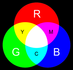
	greenLB= (50,100,0)
        greenUB = (100, 255, 140)

        redLB = (169,136,103)
        redUB = (179,225, 206)

        yellowLB = (10,50,100)
        yellowUB = (80,230,230)

        if(findColor == "red"):
                colorLB = redLB
                colorUB = redUB

        elif(findColor == "yellow"):
                colorLB = yellowLB
                colorUB = yellowUB

        elif(findColor == "green"):
                colorLB = greenLB
                colorUB = greenUB
        else:
                colorLB = blackLB
		colorUB = blackUB

	hsv = cv2.cvtColor(image, cv2.COLOR_BGR2HSV)
        mask = cv2.inRange(hsv, colorLB, colorUB)
        mask = cv2.erode(mask, None, iterations =2 )
        mask = cv2.dilate(mask, None , iterations =2 )

	# Ensure no stray element is detected as tag
	contours = cv2.findContours(mask.copy(), cv2.RETR_EXTERNAL, cv2.CHAIN_APPROX_SIMPLE)[-2]

        for c in contours:
                if cv2.contourArea(c) > pixel_size:

        ################# CENTROID OF THE TAG ##################
                        M = cv2.moments(c)
                        cx = int(M["m10"]/ M["m00"])
                        cy = int(M["m01"] / M["m00"])

			# Define contour and center
                        cv2.drawContours(image, [c] , -1, (0,255,255), 2 )
                        cv2.circle(image, (cx,cy), 7, (255,255,255), -1 )

	# Display on console for debugging
        #cv2.imshow("RAW", imageRaw)
        #cv2.imshow("Threshold", mask)
        #cv2.imshow("overlay", image)

        print cx, cy
	key = cv2.waitKey(1) & 0xFF
        rawCapture.truncate(0)
	
        if( key == ord("q") ):
                break

	print needsWater
	print state
	print findColor

###################### STATE MACHINE #########################

	# STATE 0: Initializing
	if state == 0:
		if needsWater == []:
			findColor = 'black'
			cx = -1
			cy = -1
		elif needsWater[0]=='sensor2':
			cx = -1
			cy = -1
			state = 4
			findColor = 'red'
		elif needsWater[0] == 'sensor1':
			cx = -1
			cy = -1
			state = 2
			move = 1
			findColor = 'green'
		elif needsWater[0] == 'sensor3':
			cx = -1
			cy = -1
			state = 1
			move = 1
			findColor = 'yellow'
		else:
			findColor = 'black'
			cx = -1
			cy = -1
	
	# STATE 1:  Turn Left towards Yellow/Sensor3
	elif state == 1:
		if cx > 0 and cy > 0:
			state = 3
		elif move == 1:
			turnLeftSlow(0.3)
			now = time.time() + 1
			move = 0
		elif time.time() >= now:
			move = 1
		else:
			pass

	# STATE 2: Turn Right towards Green/Sensor1
        elif state == 2:
                if cx > 0 and cy > 0:
                        state = 3
                elif move == 1:
                        turnRightSlow(0.2)
                        now = time.time() + 1
                        move = 0
                elif time.time() >= now:
                        move = 1
                else:
                        pass
	
	# STATE 3: Adjusting
	elif state == 3:
		if cx < (halfScreen*1.1) and cx > (halfScreen*0.9):
			if findColor == 'yellow' or findColor == 'green':
				state = 4
			elif findColor == 'red':
				state = 0
			else:
				pass

		elif cx > (halfScreen*1.1) and adjust == 1:
			turnRightSlow(0.1)
			adjust = 0
			adjustTime = time.time() + 1
		elif cx < (halfScreen*0.9) and adjust == 1:
			turnLeftSlow(0.1)
			adjust = 0
			adjustTime = time.time() + 1
		else:
			if time.time() >= adjustTime:
				adjust = 1
	
	# STATE 4: WATERING PLANT
	elif state == 4:
		
		# Lowers arm and turns on pump
		moveArm(0.7)
		GPIO.output(pump, True)
		time.sleep(1)

		# Turns off pump and raises arm
		GPIO.output(pump, False)
		backArm(0.6)

		# Remove from queue
		if(findColor == 'red'):
			needsWater.remove('sensor2')
			print 'Was here'	
		elif(findColor == 'green'):
			needsWater.remove('sensor1')
			print 'remove sensor1'
		
		elif(findColor == 'yellow'):
			needsWater.remove('sensor3')
			print 'remove sensor3'
		else:
			pass
		state = 5	

	# STATE 5: Return to center
	elif state == 5:
		if findColor ==  'yellow':
			findColor = 'red'
			cx = -1
			cy = -1
			state = 2
		elif findColor == 'green':
			findColor = 'red'
			cx = -1
			cy = -1
			state = 1 
		# If red
		else:
			state = 0
			cx = -1
			cy = -1
			findColor = 'black'
	  
Parts Cost
Water Pump $9.99
Vinyl Tubing $6.20
5pc Moisture
Sensors
$7.99
12V Battery Holder $8.00
5V Relay Module $5.80
2pc Continuous Rotation
Servos
$20.00
Acylic Robot Base
Design
INFO 4410
Project
Raspberry Pi 3 Model B ECE 5725
Other Parts Scrap

Main Content

Contributions and Contact

Srinivasan designed and implemented the tag recognition module using RasPi Camera and openCV. Albert designed and built the robot base in the INFO 4410 class with a team. Circuit design and initial mechanical subsystem testing was done by Albert. State machine development and testing were done by both Srini and Albert.

We would like to give thanks to the INFO 4410 class for the pre-built robot which was extremely useful and convenient to build on. We would also like to thank Mark (Moonyoung) Lee (ml634@cornell.edu) and Peter A. Slater (pas324@cornell.edu) for their previous work with color detection and centroid calculations in their Robot Candy Sorter project. Finally, we would like to give special thanks to Professor Joe Skovira for his guidance and help in completing our project.