Anti-Snooze-Alarm-Clock
David Li (dhl72) & Ju Seong Kim (jk2528)
Project Report Submission: May 18th, 2017
Objective
For most people, waking up promptly at the first instance of the alarm in the morning is one of the hardest things to do each day. We are always tempted to snooze because we feel groggy and don't feel ready to tackle the day yet and the not-yet-conscious-brain constantly coaxes us into believing that just 5 more minutes of sleep will make all the difference. However, the act of dipping in and out of sleep by snoozing messes up the internal clock within our body and can make our day more draining and exhausting, according to many physicians.
Since this problem is so common in today's civilized society, we wanted to create a mobile alarm clock that can run away to force the sleeper to get out of bed, stand on his or her two feet, and actively chase it to turn off the annoying alarm. With this short accidental exercise, thanks to a new mobile alarm clock, the person is ready to start the day feeling more alert than bygone days.
Introduction
We've all been there. That moment when the alarm clock rings in the morning and it feels like you're getting hit on the head with a jack-hammer and you feel the irresistible urge to hit that snooze button to get the sweetest 10 minutes of extra sleep, which often turns into 1 or 2 hours... Because this problem is so common and relevant to today's college students, especially at Cornell (where the weather isn't usually great), we wanted to create a gadget that can solve this problem. We present to you our Anti-Snooze Alarm Clock: our solution to one of many problems of modern day college students.
Our Anti-Snooze Alarm Clock is essentially a mobile autonomous robot with basic functionalities of an alarm clock. The system consists of the Raspberry Pi 3 (the central microcontroller), piTFT screen (for user interface), the motor control (for robot's movement), the Speaker (to annoy the sleeper), RTC (Real-Time Clock) module (to keep track of time offline), PIR Motion sensor (for robot to recognize that the sleeper is trying to grab it so that it can decide to run away), and IR sensor (for robot to detect object in its path to avoid collision). The diagram representing our system composition and the picture of our finished product is shown below.

Figure 1: Finished Product

Figure 2: Diagram Representing our System Composition
Design
MOTOR CONTROL SUBSYSTEM
The motor control subsystem consists of 2 DC motors, a single L293D quadruple half-H drivers (H-bridge) for controlling the direction of rotation for the two motors, and a 3.3V to 5V voltage converter chip to accommodate the 3.3V control signals coming out from Raspberry Pi going into the H-bridge chip, which operates at 5V. The diagram representing the overall motor control subsystem circuit is shown below along with the picture of the finished circuit.


The motor control subsystem utilizes 4 GPIO pins from the Raspberry Pi to control the direction of rotation for the two motors: GPIO19 (Purple) and GPIO13 (White) for the left motor and GPIO12 (Yellow) and GPIO16 (Green) for the right motor. These 4 signals all go through a single voltage converter chip and get converted from 3.3V signal to 5V signals. The schematics and the truth table for the voltage converter chip (adapted from SN74AHCT125 data sheet from Texas Instruments) are shown below.


As can be seen from the schematics above, this chip was perfect for our motor control subsystem because we needed voltage conversion for 4 signals and this single chip had exactly 4 buffers. As a result, this made it very convenient to build a simple and compact system. The signal that came out from the GPIO19 (Purple) was wired to Pin 12 (4A), GPIO13 (White) wired to Pin 9 (3A), GPIO12 (Yellow) wired to Pin 5 (2A), and GPIO16 (Green) wired to Pin 2 (1A). Based on the function table shown above, OE(bar) is the signal that enables each of the buffers. Since we were simply relaying the signals coming out from the Raspberry Pi to the H-bridge chip, we decided to set each of the enable signals to be LOW by grounding the pins to enable the buffers permanently. Thus, pins 1 (1OE(bar)), 4 (2OE(bar)), 10 (3OE(bar)), and 13 (4OE(bar)) were all connected to the common GND (which originated from the GND pin of Raspberry Pi) along with pin 7 which is the master ground pin on the voltage converter chip. Pin 14 (VC C) was connected to the 5V voltage source from Raspberry Pi.
After these wirings, the outputs that originate from Pins 3 (5V signal for GPIO16), 6 (5V signal for GPIO12), 8 (5V signal for GPIO13) , and 11 (5V signal for GPIO19) were voltage compatible to work correctly when wired to the corresponding pins of the H-bridge. The schematic, the truth table, and the pinout diagram of the L293D quadruple half-H drivers (adapted from the datasheet from Texas Instruments) are shown below.


There are many ways in which this H-bridge can be put to use. Each of the 4 half-H bridges can be used to drive motors in one directions. However, for our purposes, we used the chip as two sets of bipolar stepping-motor control, using 2 half-H bridges for each motor for bidirectional rotations. Ultimately, our left motor made use of the right side of the circuit diagram shown above and our right motor was controlled by the left side of the circuit diagram. Pins 4, 5, 12, and 13 are grounded. Pin 16 is the supply voltage pin for the chip, which takes in 5V from the 5V pin on the Raspberry Pi. This supply voltage pin is connected to pins 1 and 9 enable the half H-bridges on left side and right side of the chip respectively. Pin 8 is connected to the positive terminal of the supply voltage for the DC motors (6V AA battery pack). Pin 2 is connected to GPIO16 (Green), Pin 7 to GPIO12 (Yellow), Pin 10 to GPIO13 (White), and Pin 15 is connected to GPIO19 (Purple). At last, the two DC motor terminals for each motors are connected to pins 3 and 6 for right motor and pins 14 and 11 for the other motor. The diodes and capacitors were added as shown in the schematic to protect the DC motors from voltage spikes and other noises which could cause random jitters.
With this hardware setup, controlling the motors through code was very simple. We setup the GPIO pins 19, 13, 12, and 16 as output pins, after which we referenced the truth table of the bidirectional DC motor control as shown below to control the rotation direction of the motors. Based on these logic, basic MoveForward(), MoveBackward(), TurnRight(), TurnLeft(), and Stop() functions were created.

For example, for the MoveForward() code, we set GPIO13 (Pin 10 on H-bridge chip) and GPIO12 (Pin 7) to HIGH and set GPIO19 (Pin 15) and GPIO16 (Pin 2) to LOW.
.jpg "Sample Code for Motor Control")
However, after some careful considerations, we switched our GPIOs to control our motors with PWM (pulse width modulation) so that we can have better control on the speed of the motors. At the time of the development, we wanted to create multiple states for our motor speed, so that initially, the motor speed would be at state 0 (the stationary state), but when the robot detects initial movement from the sleeper, it can start moving at a relatively slower speed (state 1), but as the sleeper more actively tries to chase the alarm clock, the robot can detect faster motion and move at full speed (state 2). Unfortunately, due to limited amount of time, we weren't able to fully explore these additional states for the motor control. As a result, we operated our motors at 50% duty cycle with our PWM instantiation for move forward, backward, turn right, and turn left functionalities. 100% duty cycle caused the robot to move too fast to not give enough time for the IR sensor to respond to object fast enough to avoid collision. The details of our implementation for the motor control can be referenced from the code appendix.
SENSORS
PIR MOTION SENSOR
The PIR Motion sensor somewhat works as the keystone for the anti-snooze alarm clock. The robot uses this sensor to detect that something is moving, so it better start running away. We connected this sensor to GPIO 26 and set the Raspberry Pi pin as an input. The reliability of the PIR motion sensor was not optimal possible due to its close proximity with the DC motors. The close proximity may have introduced noise that affected our navigation algorithm due to detecting motion at certain times when there was none. We remedied that problem by introducing a software 8-sample running average filter with thresholding to determine whether there was actually motion detected. This acted as a form of electrical debouncing for the signal and was effective at reducing the rate of false detections.IR SENSOR
The IR sensor is used to detect any object in the way of the robot to prevent the gadget from running into objects.SOUND SUBSYSTEM
In our system, the sound subsystem functionally serves as the primary means to wake up the user from his or her sleep. When considering implementation, we prioritized form factor and sound quality as the two design characteristics to optimize. Form factor of the speakers is important to our system for ease of integration in the alarm clock because we intended for the alarm clock to be small and mobile. Coupled with the need to integrate sound, displays, and motors into one miniature robot, the smaller the speakers were, the easier it likely would be to integrate. Sound quality is important to our system because the speakers provide the sole method of waking up the user. Thus we needed to ensure that a minimum threshold of volume could be met and that speakers provided sufficient sound quality when provided highly sampled music files. We thought sound quality could also play a role should custom alarm tones be a feature for users.
We chose ultimately to move forward with Mini External USB Stereo Speakers. This model was chosen for its small form factor and simplicity of integration with the Raspberry Pi while still providing a moderate upgrade in sound quality. The speakers are powered by USB which work well in conjunction with the powered USB slots found on the Pi 3 we used for the project and in this class. This eliminated the need an external power circuit for the speakers which had potential to reduce the total space required for implementation of sound. The speakers were designed to be plug and play with the Pi and came with a compatible USB sound card. The USB sound card provided a better quality compared to the default BCM sound card for the Pi.
The process of configuring the speakers with the Pi involved configuring the settings for ALSA utilities to recognize the USB sound card as the default sound card. The general process of configuring ALSA to recognize the USB speakers as the default audio output involved updating a series of ALSA’s configuration files to recognize and default to the USB speakers. The two files necessary to update are /usr/share/alsa/alsa.conf and ~/.asoundrc.
Once the speakers were properly configured as the default audio device, audio functions we intended to implement into the project were were incrementally tested until we could run them within the python script. This was accomplished by taking advantage of the os library (or alternatively the subprocess library could be used as well) to utilize the mpg123 utility to play audio files in the background. The command amixer, the command prompt version of alsamixer, was used to control the output audio volume.
When integrated with the system, music was implemented by spawning a background process that looped through the alarm sound file and having the python script adjust the volume between 0 and 30 % output respectively.
TIME SUBSYSTEM
The time subsystem is used to keep track of time and set alarms. The high level implementation of our time subsystem utilizes software to keep track of alarm times set by the user by writing those inputs to files and to check those files against the date and time provided by the hardware real-time clock (RTC). The rationale to use a real-time clock is that most alarm clocks keep track time without needing connection to the internet. However Linux does not employ a real-time clock for purposes of cost and thus keeps track of time solely by syncing to the network. Because we had a product design mindset when we approached the project, one assumption we could not make was that all users would have access to the internet at all times. Utilizing a real-time clock not only enables the alarm clock to operate off the network but also makes it resilient to power cycling of the Raspberry Pi because the RTC runs on a separate coin battery.
We built the software implementation on the assumption that power cycling may be common such as when batteries die and must be replaced. In these cases, we do not want to lose the settings the user had set for their alarm clock for simplicity of use. Thus keeping track of alarm variables within a python script process is not sufficient because that information can be easily lost. A more permanent way to storing this information is to write it to a file. We decided to utilize Linux’s environmental variables to store and express the alarm clock information. We would export the last set alarm value into the python environment and have the alarm clock python process check the environmental variable during initialization and modify the environmental variable and file during operation. To account for power cycling, we stored this information in ~/.profile which is executed on bootup via exporting a specific environmental variable and updated via appending the file. We took advantage of the sys python library to interact with environmental variables.
The difficult part of this implementation was implement functions able to interpret environmental variables in the context of our design. Despite having a library able to read environmental variables, we still needed to implement functions to handle information parsing and bounds checking to enable options such as setting periodic alarms and accounting for day and hour overflow when the snooze functionality is utilized. The functions can be found in the code’s METHODS section that can be downloaded in the Appendix.
One weakness of our implementation is that the ~/.profile may become larger over time due to continuously appending. During testing we noticed no noticeable effect and periodically manually deleted portions of file. Some fixes to this are suggested in the Future Work section.
GUI
Similar to in Lab 3, we built a GUI environment for the user to interact with the alarm clock with the pygame library. The GUI is meant to enable the user to interact with the alarm clock to set an alarm time, read the current time and date, and stop or snooze the alarm when it is triggered. The GUI is implemented on the piTFT and utilizes its resistive elements to implement a touchscreen. The user then can interact with our program via the piTFT’s touchscreen. This section will provide an overview of the three screens or menus we implemented in the GUI. For more information regarding implementation of software, refer to the code in the Appendix.
The default screen displays the date, time, and the options to either set an alarm time or exit alarm clock program. In practice the exit option need not exist but was useful for debugging or exiting the program when testing.
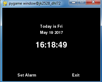
Figure 3: Default Alarm Clock Screen
When the set alarm time is triggered and the audio for the alarm is played, the display on the piTFT will change into displaying only the current time and the options to either snooze and turn off the alarm. Selecting either option will return the user to the default alarm clock screen.
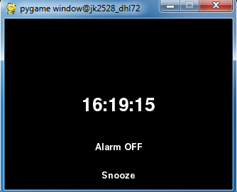
Figure 4: Alarm Triggered Clock Screen
When on the initial screen, selecting the option to set alarm brings the following display into view. The display shows time in the center that can be modified using buttons on the left or right of the time. The buttons provided enable the user to increment or decrement the hour or minute field of the displayed time. The display also has two options in Set and Cancel. Pressing Set will set the next alarm to trigger at the time set in the center of the display. Pressing cancel will keep the previous alarm time and return the user to the default alarm clock screen.
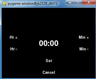
Figure 5: Set Alarm Menu
Testing
MOTOR CONTROL SUBSYSTEM DEVELOPMENT
The motor control subsystem was developed incrementally. First, the motors were tested to see that they were functional. We simply applied 5V to the motors using the DC Power Supply in the lab. After verifying that the motors were working, we wanted to make sure that our H-bridge was performing nominally. Initially, we began to test one side of the H-bridge (1 through 8 and 16). At this point, we were still using the in-lab DC power supply for 5V source and 6V source (to power the DC motor). This gave us the chance to get a grip on how the L293D chip worked.
After we got one side of the H-bridge to work, we installed the second motor to the other half of the H-bridge chip as shown below and we played around with the input combinations at pins 2, 7, 10, and 15 to simulate moving forward, moving backward, turning left and right functionalities.

After making sure that the H-bridge and the motors were working correctly, we proceeded to check that the voltage converter was working correctly. This was done using both the oscilloscope and the DC power supply in the lab. Each of the 4 buffers in the chip were tested for nominal performance. For example, for buffer number 1, pin 1 was set to GND (to enable the buffer) and 3.3V signal was injected into pin 2 and pin 3 was checked to see if it really outputted voltage close to 5V. After the functionality was verified for all 4 buffers, we began to carefully connect the 4 GPIO pins from Raspberry Pi to the corresponding pins on the voltage converter chip. Then the corresponding outputs pins from the voltage converter were connected to corresponding input control pins on H-bridge chip. The final testing phase setup for the motor control is shown below

Then we ran simple code to see if we can control the DC motors with Raspberry Pi.
SOUND SUBSYSTEM TESTING
The Adafruit tutorial suggests updating the /etc/asound.conf file however we found that method insufficient for the OS recognize the USB as the default audio device. Instead the correct two files to be updated (based on our situation) are /usr/share/alsa/alsa.conf and ~/.asoundrc. This was successful in making the USB speakers the default audio playback device except for a few rare instances where the audio would default back to the sound card. In these cases we found ~/.asoundrc had reverted the changes we made and would need to be rewritten to.
The incremental unit testing process is as follows:
- Checked that alsamixer recognized PCM as the default sound option. This can be confirmed using F6 in the utility to view all sound output options and checking whether the initial sound meter corresponds to the USB speaker. The alsamixer command provides a graphical interface for controlling properties of sound cards and devices.
- Performed initial sound test on speakers by generating white noise.
- Tested using mpg123 to run an alarm .mp3 file.
- Replicated volume control using amixer commands.
- Replicated test functionality within python script.
During the unit testing phase we encountered very few issues. The only major issue encountered was the loss of audio output when running commands as a superuser. However this issue wasn’t explored much further as it wasn’t necessary for integration in our design.
During integration with the rest of the system we ran into a major issue in which the sound card was no longer recognized by the OS and this resulted in a lack of audio output. The underlying cause was discovered to be the interaction between the Linux ALSA sound utility and its interaction with the pygame library. The pygame library has an .init() function that initializes all modules. Although the function is practical to use in general to take advantage of the entire pygame library, that said library has a few modules that interact directly with sound such as pygame.mixer and pygame.mixer.music. Likely those libraries have configuration commands during their initialization that interfere with ALSA. This problem was resolved by independently initializing modules of pygame related to animation. An alternative method could have been to use the pygame utility to stream music rather than the mpg123 utility.
TIME SUBSYSTEM TESTING
We incrementally tested each high level function in a test script prior to integrating with the graphical interface and the rest of the system. No major issues were encountered during implementation. The following provides a list of all functions related to alarm clock parameters:
- parse_date(): Returns date in list in following format: [Weekday, Month, Day, Time, TimeZone, Year]
- get_alarm_time(): Returns currently active alarm time in following format: [Day, Time]
- set_alarm_time(Weekday, Hour, Minute): Sets environmental variable to set an alarm time in case of power cycle. Resets local environmental variable and also appends to ~/.profile to ensure changes are permanent through power cycling.
- snooze(minutes):Snooze for minutes Minutes.
Results
For the final demo we showcased an alarm clock robot with a GUI interface implemented on the piTFT capable of detecting human motion and deterministically moving to avoid capture. Additionally the robot was able to avoid collisions with obstacles in its path using the IR sensor and deterministically reroute its path to continue to avoid capture.
When we first proposed the project, we suggested a robot that with a functional alarm clock that moves away from you stopping when an object is hit as a baseline goal. We met that goal successfully. Additionally we had proposed a concept of an expanded demo which was a “smart robot that sounds the alarm and moves erratically while avoid objects in the room aimed at annoying the user and forcing him to get out of bed.” We were not ultimately able to complete all the functionalities described in our expanded demo. Despite that we were able to complete some of the work we aimed to accomplish for the expanded demo. For example, we able to implement basic navigation capabilities for our robot past simply stopping when it encounters an object. Using IR sensors, the robot was able to detect objects in its path and perform a simple reroute to a different direction.
In the process of creating and testing our robot we discovered that there were some performance optimizations that could have been made. The optimizations will be covered in Future Work sections of the report.
Conclusion
Overall we were to achieve a functional prototype of our alarm clock concept. The project integrated several of Linux’s features that we learned throughout the semester such as the use of environmental variables, configuration of GPIO for flexible purposes, and the use of pygame for animation. Additionally we were able to explore some new features of Linux such as using the os library to call Linux functions within scripts, using real-time clocks to augment the capabilities of the Linux system, and using the ALSA sound system.
The only features that definitely were not fully compatible in our design were the pygame library and the ALSA sound utility. Although we remedied this by not initializing all features in the pygame library, a more effective method would be to utilize the music and sound libraries within pygame. Additionally we discovered that running a looping mpg123 process and only modifying volume was only effective to a point. With the sleep time parameter we implemented, there are occasionally cases in which motor actions were delayed slightly which we compensated by running the DC motors are slower speeds. However to improve performance past this point, conditional music thread spawning would likely be necessary.
On the physical side of our project, there were cases in which our PIR sensor detected incorrect values which we believe is attributed to high frequency noise generated by the use of our DC motors. Although we implemented a software fix, in practice creating a noise isolation circuit would resolve the issues more completely.
Future Work
Given more time there are several areas we would have liked to explored to improve our Anti-Snooze Alarm Clock’s quality and capabilities. To make the alarm clock more difficult to catch, it would have been interesting to explore the use of pseudo-random functions to generate variable motor speeds in order to have random movement. Additionally, as mentioned in the previous section, creating a noise isolating circuit for the PIR sensor would have improved the reliability of our navigation algorithm. The pacing of the schedule also made us reluctant to attempt to learn how to integrate sound using the modules the pygame library provided us. Utilizes the pygame library’s modules may present possibility to improve overall performance by implementing sound within the script rather than as an OS function call that would spawn an additional process. On the topic of music, implementing an interface for users to upload alarm tones they wish to be used to wake up to would have been an interesting feature as well. Finally an improvement to how we stored alarm parameters would be to create an alternative file rather than using ~/.profile. That way the file can be rewritten to and overwritten to conserve memory without deleting user configurations.
Improving the structural design of the alarm clock would be necessary in a hypothetical commercial setting as some of the methods we used to integrate all the hardware is not reliable over long periods of time (such as electrical tape).
Cost Breakdown
| Material | Price |
|---|---|
| 2 DC Motor | $4.00 X 2 = $8.00 |
| IR Sensor | $5.95 |
| PIR Motion Sensor | $9.95 |
| Diodes/Capacitors (aggregate) | $1.00 |
| L293D H-Bridge | $3.55 |
| SN74AHCT125 Voltage Converter | $0.39 |
| Adafruit PCF8523 Real Time Clock Assembled Breakout Board | $4.95 |
| Mini External USB Stereo Speakers | $12.50 |
| CR1220 12mm Diameter - 3V Lithium Coin Cell Battery | $1.00 |
| Total | $47.29 |
Work Distribution
David Li: Assisted in creating and implementing navigation algorithm, implemented sound, time, and GUI subsystems. Created method for software filtering of PIR sensor readings.
Ju Seong Kim: Implemented and integrated the motor control subsystem and the PIR/IR sensors. In charge of the final assembly and structural aspect of the robot.
References
The H-bridge Datasheet
Voltage Converter Datasheet
PIR Motion Sensor Datasheet
IR Sensor Datasheet
Configuring Pi (Jessie) to recognize USB speakers as primary output audio device.
Initial idea on how to work around interference between ALSA and PYGAME.
PYGAME documentation used to reference modules and research issue.
Contact
David Li (dhl72@cornell.edu) & Ju Seong Kim (jk2528@cornell.edu)
Acknowledgements
We would like to take the time to thank Dr. Joseph Skovira and the course TAs: Brendon Jackson, Steven Yue, and Jacob George for all their help and guidance throughout the course and during the development of this final project.