Design and Testing
Lock Screen
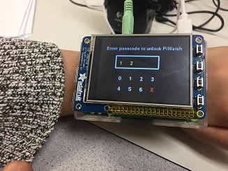
The first part of the PiWatch that was implemented was a numerical passcode enabled lock screen. Three functions were written to help draw the lock screen, control button presses on the screen, and check whether the entered passcode matches a stored passcode of 4 digits. Globally, a few variables were defined that were critical to the lock screen, including the following: 'lock', which stored information on whether the watch is locked or not, 'passcode', which was a list of length 4 storing the correct passcode digits, passcode_error',which said whether an entered passcode matched 'passcode' or not, and 'currently_entered', which was a list (initialized as empty) that stored the digits that the user entered while in the lock screen.
The layout of the design for the lock screen was planned out first. It was decided to have two rows of numbers, to include the numbers 0-6, and to include a X button to allow the user to delete the most recently pushed digit in the passcode. A rectangular box was also planned out to show the digits entered for the passcode, and user prompts were also planned out as text drawn at the top of the screen. Once the placement of all of these elements was decided, global variables representing the starting x and y coordinates for the elements as well as delta x and y values (representing the spacing between elements) were set. Then, a function called draw_lock_screen() was defined, and it was called in the main infinite while loop only when the global variable 'locked' was set to 1. The two inputs for this function included a variable called 'error', representing if the passcode was entered incorrectly once 4 digits were pressed, and 'timer_red', which is a signal from the PiTime app (refer to the PiTime's page to learn more about this variable).
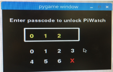
For the main text at the top of the screen, the input variable 'error' was checked. If a passcode of length 4 had not yet been pressed (i.e. error=0), then a message prompting the user to enter the passcode is drawn onto the screen. Otherwise, if error is 1, then red text notifying the user that the entered passcode was incorrect and to try again was displayed. Once this was decided, using the coordinates and deltas stored as global variables, the main numberpad and the delete button ('X') were drawn. A rectangle with a white border (where the entered digits are displayed) was also drawn, and any digits stored in the global list 'currently_entered' are parsed and displayed within this box.
In order to store what digits on the numberpad were pressed by the user at any given time, another function called passcode_press() was defined. Globally, this was called when a press and release of the TFT screen by the user's finger was detected. Inputs to this function included the x and y coordinates of the press and the global passcode 'error' variable. If the coordinates of the detected press were within any of the coordinates used to draw the numberpad buttons, the corresponding number (in string form) was appended to the global 'currently_entered' variable. If the 'X' button was displayed, the last element in the list was removed using .pop(). For all instances, the variable 'error' was set to 0, to reset the variable when the user is re-entering the passcode after getting an incorrect code message.
In the global infinite while loop, if 'currently_entered' reached a length of 3, a third function named check_passcode() was called. It was defined to have 'currently_entered' as the only input. Within the function, it compared each element in 'currently_entered' to 'passcode'. If correct, the global variable 'locked' was set to 0 via a return statement; if not, it was maintained at 1, and the 'passcode_error' variable was set to 1 (to notify the draw_passcode() function to draw the error message in the next iteration of the while loop). For both cases, 'currently_entered' was reset to an empty list. The screen was updated accordingly.
Along with this software implementation, GPIO pin 17 served as a physical button that locked the watch and returned the user to this screen.
Testing was performed on the Pi desktop since this allowed for precise clicks with the mouse to verify all behavior before proceeding to test on the piTFT. An image from one of these tests can be found in Figure A.
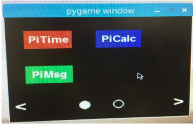
Upon the 'locked' variable becoming 0 (after the correct passcode was entered), the user was transitioned to the home screen. Similar to the lock screen, there were two main functions defined: a drawing function and a button press detection function.
The home screen layout was designed with two total app screens (to simulate how users can scroll between pages of apps), one containing three of our app icons and the other containing the other two icons. To implement the scrolling between the two pages, buttons displaying as forward and backwards arrows at the bottom corners of the screen were planned out. Included with these were two circles representing the two pages, with one of the circles filled in (representing the current screen) and one hollowed. Like for the lock screen, global variables defining the starting x and y coordinates as well as delta x's and delta y's for all app icons, page circle icons, and buttons. Rectangles were drawn in the appropriate places to represent the app icons, with each app colored differently.
For press detection, a function called hs_press() was defined that took in the x and y coordinates of a touch screen press, the page number (1 or 2) of the home screen (called 'hs_number'), and a variable (called 'current_app') representing the app currently being run as inputs. The 'current_app' variable was initially set to 99 globally (representing the home screen) and was updated according to where the user pressed and on what page the app is on. If the appropriate bottom arrow button was pushed, the variable 'hs_number' and the bottom two circles were modified to reflect this page change.
GPIO pin 22 served as a physical button that returned the user to the home screen from any app.
Testing was performed on the Pi desktop since this allowed for precise clicks with the mouse to verify all behavior before we then proceeded to test on the piTFT setup. An image from one of these tests can be found in Figure B.