Appendices
Appendix A
The group approves this report for inclusion on the course website.
The group approves the video for inclusion on the course youtube channel.
Appendix B - Raw Code
arduino_control.ino
// Aruidno Control
// This program is uploaded to Arduino in order to control the radio controller


// assign 4 pins for 4 directions
int right = 6;
int left = 7;
int forward = 2;
int reverse = 5 ;

// duration time for signals
int time = 50;

// set initial command
int command = 0;

void setup() {
  pinMode(right, OUTPUT);
  pinMode(left, OUTPUT);
  pinMode(forward, OUTPUT);
  pinMode(reverse, OUTPUT);
  Serial.begin(115200);
}

void loop() {
  //receive command from laptop
  if (Serial.available() > 0){
    command = Serial.read();
  }
  else{
    reset();
  }
   send_command(command,time);
}

void right(int time){
  digitalWrite(right, HIGH);
  delay(time);
}

void left(int time){
  digitalWrite(left, HIGH);
  delay(time);
}

void forward(int time){
  digitalWrite(forward, HIGH);
  delay(time);
}

void reverse(int time){
  digitalWrite(reverse, HIGH);
  delay(time);
}

void forward_right(int time){
  digitalWrite(forward, HIGH);
  digitalWrite(right, HIGH);
  delay(time);
}

void reverse_right(int time){
  digitalWrite(reverse, HIGH);
  digitalWrite(right, HIGH);
  delay(time);
}

void forward_left(int time){
  digitalWrite(forward, HIGH);
  digitalWrite(left, HIGH);
  delay(time);
}

void reverse_left(int time){
  digitalWrite(reverse, HIGH);
  digitalWrite(left, HIGH);
  delay(time);
}

void reset(){
  digitalWrite(right, LOW);
  digitalWrite(left, LOW);
  digitalWrite(forward, LOW);
  digitalWrite(reverse, LOW);
}

void send_command(int command, int time){
  switch (command){

     //reset command
     case 0: reset(); break;

     // single command
     case 1: forward(time); break;
     case 2: reverse(time); break;
     case 3: right(time); break;
     case 4: left(time); break;

     //combination command
     case 6: forward_right(time); break;
     case 7: forward_left(time); break;
     case 8: reverse_right(time); break;
     case 9: reverse_left(time); break;

     default: Serial.print("Inalid Command\n");
    }
}
picamera.py
# Picamera
# This program is to drive Picamera and set the resolution 320 * 240 and 10 fps,
# using socket communicatin to connect with laptop

import io
import socket
import struct
import time
import picamera


try:
    with picamera.PiCamera() as camera:
        # scale down the resolution to 320 * 240
        camera.resolution = (320, 240)
        # the speed of camera is 10 fps
        camera.framerate = 10
        time.sleep(1)                       \
        start = time.time()
        stream = io.BytesIO()

        # set the format as jpeg
        for foo in camera.capture_continuous(stream, 'jpeg', use_video_port = True):
            connection.write(struct.pack('L', stream.tell()))
            connection.flush()
            stream.seek(0)
            connection.write(stream.read())
            if time.time() - start > 400:
                break
            stream.seek(0)
            stream.truncate()
    connection.write(struct.pack('L', 0))
finally:
    connection.close()
    client_socket.close()

# using socket to connect to laptop
client_socket = socket.socket(socket.AF_INET, socket.SOCK_STREAM)
client_socket.connect(('10.148.9.214', 8000))
connection = client_socket.makefile('cam')
sensor.py
# sensor
# This program is set the pin for ultrasonic sensor and
# sending the sensor data to laptop using socket connection
from socket import *
import time
import RPi.GPIO as GPIO

GPIO.setwarnings(False)
def measure():
    GPIO.output(GPIO_TRIGGER, True)
    time.sleep(0.001)
    GPIO.output(GPIO_TRIGGER, False)
    start = time.time()
    while GPIO.input(GPIO_ECHO)==0:
        start = time.time()
    while GPIO.input(GPIO_ECHO)==1:
        stop = time.time()
    elapsed = stop-start
    distance = (elapsed * 34300)/2
    return distance
GPIO.setmode(GPIO.BCM)
# assign TIGR pin as GPIO 5
GPIO_TRIGGER = 5
# assign ECHO pin as GPIO 6
GPIO_ECHO    = 6
# Trigger pin
GPIO.setup(GPIO_TRIGGER,GPIO.OUT)
# Echo pin
GPIO.setup(GPIO_ECHO,GPIO.IN)
# initial to low
GPIO.output(GPIO_TRIGGER, False)
try:
    while True:
        distance = measure()
        print "Distance : %.1f cm" % distance
        # send data to the host every 0.5 sec
        client_socket.send(str(distance))
        time.sleep(0.2)
finally:
    client_socket.close()
    GPIO.cleanup()
# create a socket and bind socket to the host
client_socket = socket(AF_INET, SOCK_STREAM)
client_socket.connect(('10.148.9.214', 8008))
driving_stage.py
# driving_stage.py
# car self-driving while processing a set of works including road tracking,
# traffic signs detection, and distance sensoring
import cv2
import numpy as np
import math
import threading
import SocketServer
import serial
# multi-threads for video and distance processing
class Thread(object):
def thread1(host, port):
server = SocketServer.TCPServer((host, port), SensorDataHandler)
server.serve_forever()
def thread2(host, port):
server = SocketServer.TCPServer((host, port), VideoStreamHandler)
server.serve_forever()
distance = threading.Thread(target=thread1, args=('10.148.9.214', 8008))
distance.start()
video = threading.Thread(target=thread2, args=('10.148.9.214', 8000))
video.start()
distance_data = " "
# processing sensor data in real time by thread 1
class Distance_data(SocketServer.BaseRequestHandler):
data = " "
def handle(self):
global sensor_data
try:
while self.data:
self.data = self.request.recv(1024)
distance_data = round(float(self.data), 1)
print distance_data
finally:
print "sensor connection closed"
# processing video data in real time by thread 2
class Video_data(SocketServer.StreamRequestHandler):
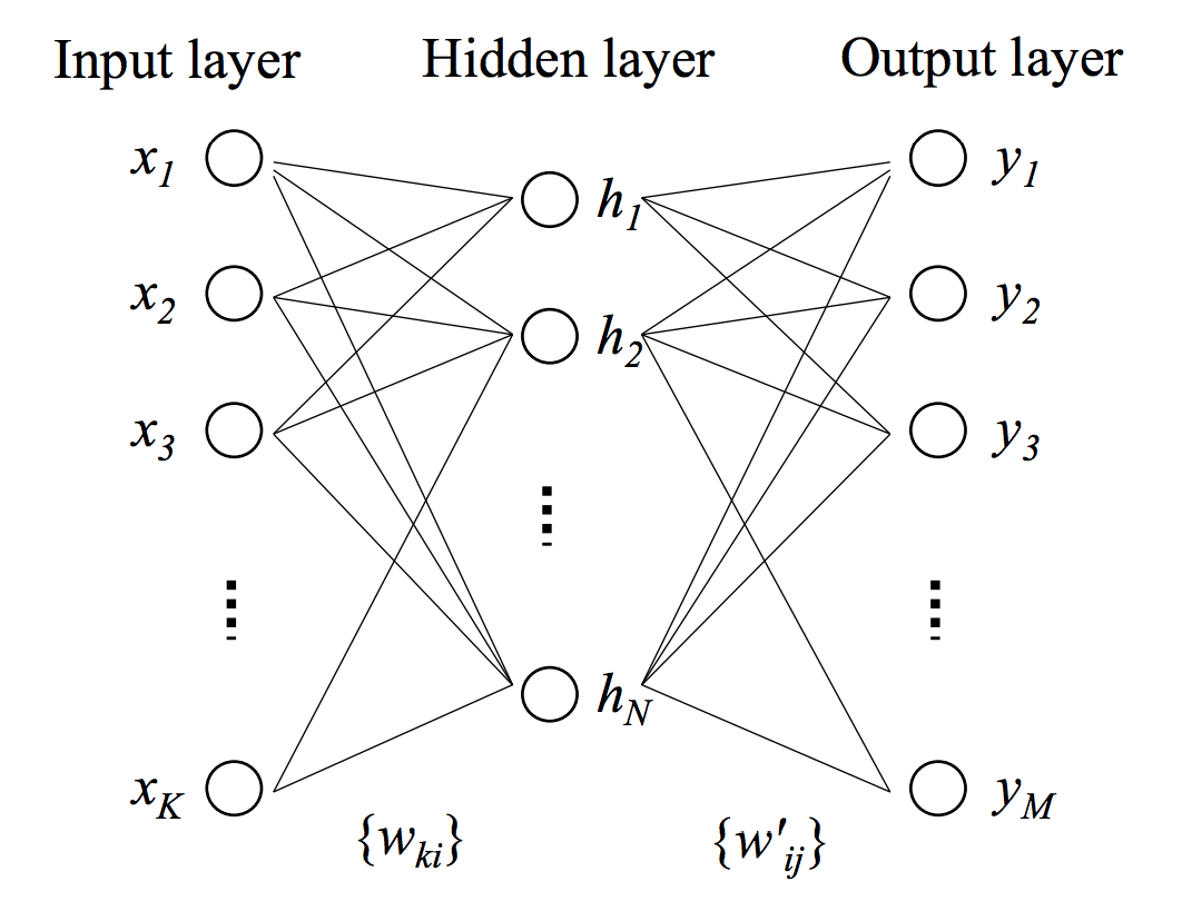
# create 3-layer ANN model
model = 3_ANN()
model.create()
traffic_sign = ObjectDetection()
self_drivingCar = Car()
h1 = 0.5 # stop sign
d_stop_sign = 25
h2 = 0.5 # traffic light
d_light = 25
# cascade classifiers
stop = cv2.CascadeClassifier('cascade_xml/stop_sign.xml')
light = cv2.CascadeClassifier('cascade_xml/traffic_light.xml')
d_camera = Distance_camera()
# time the stop time
stop_time = 0
stop_start = 0
stop_finish = 0
drive_time = 0
def handle(self):
global distance_data
stream_bytes = ' '
stop_flag = False
stop_sign = True
# stream video frames one by one
try:
while True:
stream_bytes += self.rfile.read(1024)
first = stream_bytes.find('\xff\xd8')
last = stream_bytes.find('\xff\xd9')
if first != -1 and last != -1:
jpg = stream_bytes[first:last+2]
stream_bytes = stream_bytes[last+2:]
gray = cv2.imdecode(np.fromstring(jpg, dtype=np.uint8), cv2.CV_LOAD_IMAGE_GRAYSCALE)
half_g= gray[120:240, :]
image = cv2.imdecode(np.fromstring(jpg, dtype=np.uint8), cv2.CV_LOAD_IMAGE_UNCHANGED)
# detection and distance measurement
stop_d = self.obj_detection.detect(self.stop_cascade, gray, image)
light_d = self.obj_detection.detect(self.light_cascade, gray, image)
if v_param1 > 0 or v_param2 > 0:
d1 = self.d_to_camera.calculate(v_param1, self.h1, 300, image)
d2 = self.d_to_camera.calculate(v_param2, self.h2, 100, image)
self.d_stop_sign = d1
self.d_light = d2
cv2.imshow('image', image)
image_array = half_gray.reshape(1, 38400).astype(np.float32)
prediction = self.model.predict(image_array)
# obstacle detection
if distance_data is not None and distance_data < 80:
print("Stop for obstacle")
self.self_drivingCar.stop()
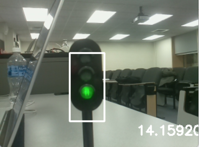
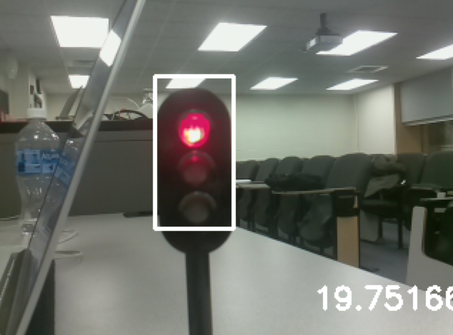
# traffic light detection
elif 0 < self.d_light < 30:
if self.obj_detection.red_light:
print("Red light")
self.rc_car.stop()
elif self.obj_detection.green_light:
print("Green light")
pass
self.d_light = 30
self.traffic_sign.red_light = False
self.traffic_sign.green_light = False
# stop sign detection, when detected, stop for 5 seconds
elif 0 < self.d_stop_sign < 25 and stop_sign:
print("Stop for stop sign")
self.self_drivingCar.stop()
if stop_flag is False:
self.stop_start = cv2.getTickCount()
stop_flag = True
self.stop_finish = cv2.getTickCount()
self.stop_time = (self.stop_finish - self.stop_start)/cv2.getTickFrequency()
if self.stop_time > 5:
stop_flag = False
stop_sign = False
# normal situation
else:
self.rc_car.steer(prediction)
self.stop_start = cv2.getTickCount()
self.d_stop_sign = 25
if stop_sign_active is False:
self.drive_time_after_stop = (self.stop_start - self.stop_finish)/cv2.getTickFrequency()
if self.drive_time_after_stop > 5:
stop_sign_active = True
if cv2.waitKey(1) & 0xFF == ord('q'):
self.rc_car.stop()
break
cv2.destroyAllWindows()
finally:
print "Video connection closed"
class ObjectDetection(object):
def __init__(self):
self.red = False
self.green = False
def detect(self, cascade_classifier, gray_image, image):
detect_f = 0
# minimum value to proceed traffic light state validation
threshold = 150
cascade_obj = cascade_classifier.detectMultiScale(
gray_image,
scaleFactor=1.1,
minNeighbors=5,
minSize=(10, 10),
flags=cv2.cv.CV_HAAR_SCALE_IMAGE
)
for (x_pos, y_pos, width, height) in cascade_obj:
cv2.rectangle(image, (x_pos+5, y_pos+5), (x_pos+width-5, y_pos+height-5), (255, 255, 255), 2)
v = y_pos + height - 5
# stop sign
if width/height == 1:
cv2.putText(image, 'STOP', (x_pos, y_pos-10), cv2.FONT_HERSHEY_SIMPLEX, 0.7, (0, 0, 255), 2)
# traffic lights
else:
roi = gray_image[y_pos+10:y_pos + height-10, x_pos+10:x_pos + width-10]
mask = cv2.GaussianBlur(roi, (25, 25), 0)
(minVal, maxVal, minLoc, maxLoc) = cv2.minMaxLoc(mask)
# check if light is on
if maxVal - minVal > threshold:
cv2.circle(roi, maxLoc, 5, (255, 0, 0), 2)
# Green light
if 5.5/8*(height-30) < maxLoc[1] < height-30:
cv2.putText(image, 'Green', (x_pos+5, y_pos - 10), cv2.FONT_HERSHEY_SIMPLEX, 0.5, (0, 255, 0), 2)
self.green = Tr
# Red light
else 1.0/8*(height-30) < maxLoc[1] < 4.0/8*(height-30):
cv2.putText(image, 'Red', (x_pos+5, y_pos-5), cv2.FONT_HERSHEY_SIMPLEX, 0.5, (0, 0, 255), 2)
self.red = True
return detect_f
# car driving
class self_drivingCar(object):
def __init__(self):
self.port = serial.Serial('/dev/tty.usbmodem14521', 115200, timeout=1)
def steer(self, prediction):
if prediction == 2:
self.port.write(chr(1))
print("Forward")
elif prediction == 0:
self.port.write(chr(7))
print("Left")
elif prediction == 1:
self.port.write(chr(6))
print("Right")
else:
self.stop()
def stop(self):
self.port.write(chr(0))
# distance measurment between camera to objects
class Distance_camera(object):
def __init__(self):
# calibration parameters
self.v0 = 119.865631204
self.ay = 332.262498472
self.alpha = 8.0 * math.pi / 180
def measurement(self, v, h, x_shift, image):
dis = h / math.tan(self.alpha + math.atan((v - self.v0) / self.ay))
if dis > 0:
cv2.putText(image, "%.1fcm" % d,
(image.shape[1] - x_shift, image.shape[0] - 20), cv2.FONT_HERSHEY_SIMPLEX, 0.7, (255, 255, 255), 2)
return dis
# 3-layer ANN model
class 3_ANN(object):
def __init__(self):
self.model = cv2.ANN_MLP()
def create(self):
neuron_size = np.int32([38400, 32, 4])
self.model.create(neuron_size)
self.model.load('data_xml/data.xml')
def predict(self, samples):
ret, resp = self.model.predict(samples)
return resp.argmax(-1)
if __name__ == '__main__':
ThreadServer()