ECE 5725 Final Project
Luxor the III
A Project By Diego Horna and Deepthi Krovvidi
Introduction
Chances are that at one point in your lifetime you have watched a Pixar movie. In every introduction they have Luxor, the lamp that jumps on top of the letter ‘i’. There’s also a two-minute short film about Luxor Sr. and Luxor Jr. Through inspiration of these iconic, animated lamps, we decided to create Luxor the III. This version of Luxor is a companion that tracks and shines light on a single object while studying or doing work. The key to tracking an object is with a Picamera and an Aruco marker. You are allowed to have nine objects with Aruco markers, but it will only track the one indicated. The user interfaces with this standalone, wireless lamp using the PiTFT screen.
Luxor the III was created for Cornell University’s ECE 5725 Embedded Operating Systems course final project. It is brought to you by Diego Horna and Deepthi Krovvidi, with the assistance of Professor Skovira and teaching assistants. This report covers all aspects of the project, from hardware and software, to final demonstration. Finally, any datasheets, documentations or forums we reference can be found in the ‘References’ section.
Objective
The objective of the ECE 5725 final project is to design a project that uses the tools learned throughout the semester and is based on the Raspberry Pi (RPi) platform. It must cost less than $100 to make, excluding the price of an RPi, PiTFT screen, charger, SD cards, and case. With these guidelines, we set out to design, manufacture and develop software to control a Pixar inspired lamp. Our goal was to have a user place an Aruco marker on any object, with the limit of nine objects, and have a lamp shine as much light as possible on that object. They could also change which object to track if there is more than one Aruco marker. Finally, we wanted to make this as compact as possible to not take up workspace.
Design
System Overview
Before we began our project, we laid out the user interaction and state space for everything we wanted Luxor the III to do. The flow chart, as shown in Fig. 1, reads in the following way: first, the user has to turn on the robot. That involves plugging the RPi its own power source and putting the switch to the ‘on’ position to power the light and servos. There is no need to start the Python program since it will start at boot-up. Next the user has to put Aruco markers on the objects they want to track, and using the PiTFT screen, indicate the number of markers they are using. Afterwards, it will begin sweeping to search for the number of indicated markers. After it has found all of them, the user has to indicate which of the objects they want it to track. Then it will go back to the last known location of that marker and begin tracking. They can switch between objects that have markers. Finally, if they are done using Luxor the III, they can select on a ‘Quit’ button and the RPi will go to its terminal. This is merely a summary of how Luxor the III works, we will go into every detail in the following section.
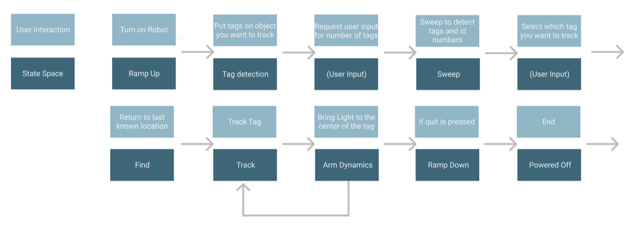
Fig. 1: User interaction and state space flow chart
Hardware
Luxor the III was designed in SolidWorks version 2017-2018. A Computer Aided Design (CAD) model of it is shown in Fig. 2. The model is missing the wiring, switch, nuts and bolts.
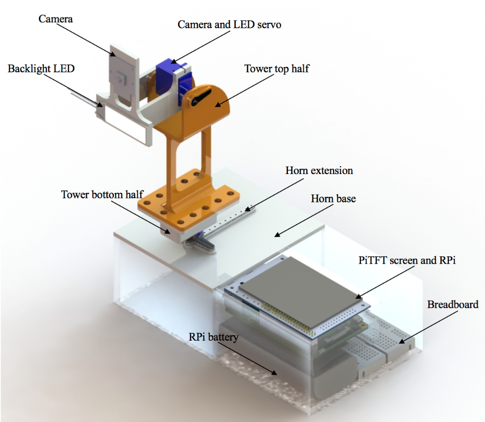
Fig. 2: CAD render of assembly with part labels
To avoid tolerance issues, the model was built as a single part. Afterwards it was broken down into several bodies for 3D printing at Cornell University’s Rapid Prototyping Lab (RPL). A total of five parts were printed: camera and light holder, tower top, tower bottom, horn extension, and horn base. The employees at RPL were the ones that decided which printer each part was printed on, all we specified was the level of quality that we needed each part to be. The total cost of 3D printing was $7.45.
Luxor the III can be separated into two main parts. The first half includes the Picamera, servos, backlight LED, switch and body. The second half contains the RPi, PiTFT screen, breadboard and lithium ion battery. They are super glued together to make it seem as one body. We used Tower SG92R micro servos for our two degrees of freedom since we needed to know and set the servo positions. It was not necessary to get metal gears since neither of them were under high loads. We used a lithium ion polymer battery of 3.7V to power both of the servos as well as the white LED backlight. We used the smallest version of the backlight available on Adafruit since it had the highest luminous intensity. Finally, we used a Picamera V2 with a 12” flexible cable adapter to have the farthest reach possible and not get tangled with other components.
All of the fasteners are M2 screws and nuts, except for the ones that hold the tower bottom half and the tower top half together. 3-32 screws and nuts were used to add weight near the servo for stability purposes. The Picamera has M2 holes which we used as through holes and to mount to the top arm. We also super glued the backlight LED to it. The top (camera and LED) servo body is free to rotate about its axis of rotation which gives us our first degree of freedom. It is mounted to both sides of the tower’s top half where one side has a fixed horn and the other a pivoting disk. Inside of the tower’s bottom half lives the second servo. This servo gives us our second degree of freedom. Its body is allowed to rotate about its axis of rotation with the horn fixed to the horn extension. The horn extension is used to provide a bigger moment arm for stability to the whole system. Finally, the horn extension is bolted down to the horn base.
The last part of Luxor the III are the Aruco markers that the user can place on various objects as shown in Fig. 3. The Aruco markers themselves are generated using the Aruco dependency Open CV library. This library contains several dictionaries for the grid size of the Aruco. The ones we picked for Luxor III are from the 6X6 dictionary. Each marker has an associated Id number that is assigned to the pattern from the dictionary. To create more robust user interface, we laser cut tiles with the associated Id number etched on the back. Each Aruco marker also has two magnets on either end with a second magnetic backing to be able to detach and reattach the marker easily.
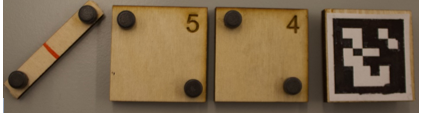
Fig. 3: Aruco markers and holders
Software
All of our code was written in Python using the Jessie operating system on a non-Preempt Kernel. Our code is structured to run from a main.py script that sets up the Graphical User Interface (GUI). This main.py script serves as our master code and runs on the PiTFT screen at boot. We did this by editing out ‘/etc/rc.local’ bash script to include our master script. All of the GUI states are shown in Figs. 3-9. If at any point the user wants to quit the program, pressing the ‘Quit’ button on the touchscreen it will take them to the RPi terminal. In addition, an emergency quit button is also built into the PiTFT. We have our main page in Fig. a, where Luxor the III gives a small introduction. Pressing ‘Next’ will take us to Fig. b. Here it indicates the user to power the servo and backlight LED by turning the switch on. A red LED light on the switch indicates that they have successfully completed the task. Next we have Fig. c, where it indicates the user to put the provided Aruco markers on objects they want to track. We limited the number of markers to nine for the number pad on Fig. d. The number pad here is used for indicating the number of Aruco markers Luxor the III has to find. For example, if the user selected ‘2’, then the servos will go from left to right and down to up to sweep for the number of markers indicated. Fig. e shows the screen that shows an error to the user and then prompts the user to input the number of markers if the entire field of view is swept and the markers are not found. Once they are located, Fig. f shows the status of each marker. The numbers in green are the markers on objects, and the ones in red are the markers that are not in use. The user can switch between markers in green if they want to track a different object. If the user decides to place a new number of markers on objects, the user can press back on the screen on Fig. f, and the screen will prompt the user to pick the number of markers placed.

Fig. 4: GUI main screen
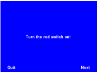
Fig. 5: Requesting user to power on backlight LED and servos
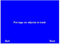
Fig. 6: Requesting user to put Aruco markers on objects to track
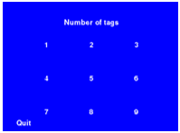
Fig. 7: Requesting user to input number of markers to search for

Fig. 8: If user does not place any markers
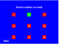
Fig. 9: Status of each marker and selection for which to track
The tracking is done using open source computer vision (OpenCV) and Aruco markers. OpenCV allows for image manipulation and analysis. The extra dependencies that were installed along with OpenCV allows for the use of Aruco markers. Open CV is used in two different locations within the main GUI script. Picamera is initialized once during the full script to prevent interfering with separate calls to camera. The first time Open CV is used, the Picamera is initialized. Using the number of markers given from the user, the sweep function analyzes each frame pulled from the Picamera. For each frame, the detected Ids are stored and compared to a master list of found Ids. If the detected Ids are already in the master list of found Ids, the servos move to the next location and check for detected Ids. If the detected Ids are not in the master list of found Ids, the Ids are added to the master list and the servos move to the next location. If the number of Ids in the master list of found Ids is equal to the number of Ids requested by the user, the sweep stops and returns the master list of found Ids. If the camera does not find any markers, the camera will ask the user to pick a new number of markers. Once the master list is returned, the PiTFT shows the available markers to track.
The second time that Open CV is used, the camera object that was previously defined is used in the tracking code. A new frame is pulled from the camera to be analyzed. For each frame, if the detected Id matches the tracking Id, the corners of the marker are used to find the center of the Aruco marker. The resolution of the field of view of the camera is set to 640, 480; therefore, the center is 320,240. The tracking algorithm returns the center of the required marker to the main GUI script. The center is then sent to the arm dynamic algorithm which calculates the new PWM required for each servo to minimize the difference between the center of the Aruco marker and the center of the field of view. An example is shown in Fig. 10.
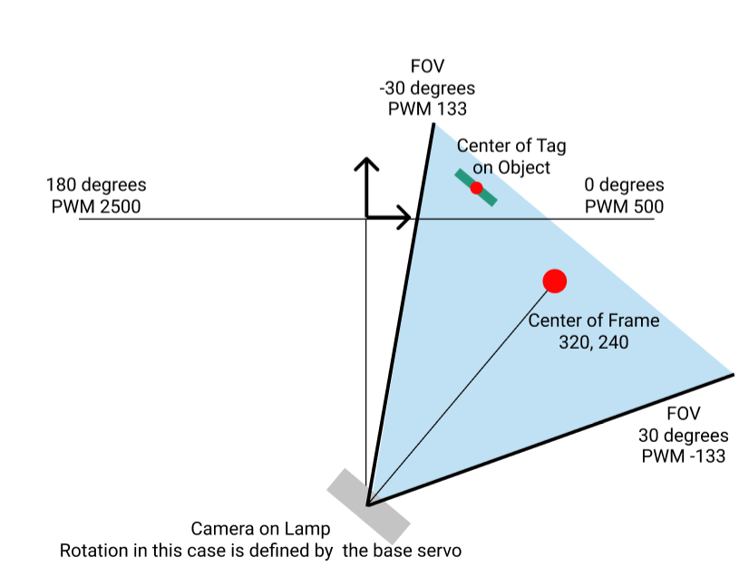
Fig. 10: Schematic of Top View Geometry to Calculate New PWM Position
If the user does not select a new marker and the marker is not removed from the field of view, the lamp will sweep again until it finds the marker and continues to track it. If the user does select a new marker, the lamp will go to the last known location of the marker, and then will go back into the loop that minimizes the distance between the two centers. After the tracking phase is begun, and the Id that was being tracked is lost, then lamp will sweep in a loop through the entirety of its field of view without prompting the user for the number of markers to track as it did prior to starting the tracking.
The code base was designed using states and external scripts that were called inside the main script. This allowed us to design, develop, and debug the full system script individually and then as a whole. Therefore, we were able to build up from solely being able to take photos with the Picamera and moving the servos to tracking the Aruco markers and having the servos move to the correct location.
Bill of Materials
As shown in Table 1, we managed to stay under the $100 budget limit.
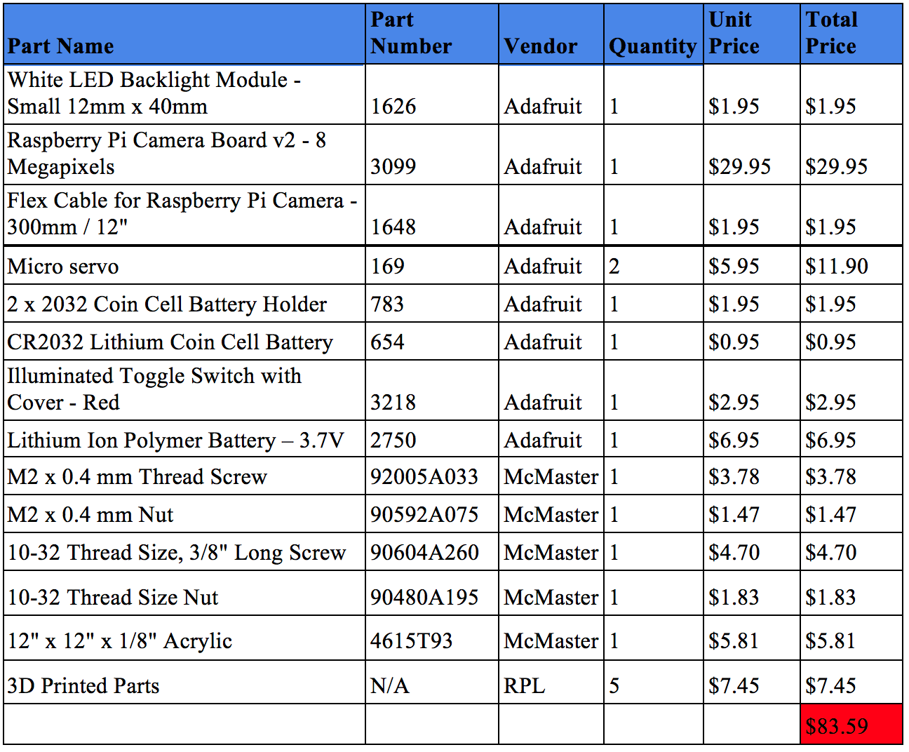
Table 1: Bill of materials
Testing
Throughout the progress of our project, we tested individual and integrated hardware and software components. First, we checked if all mechanical components fit together properly. The micro servo datasheet recommends M2 screws for the holes on its horn. However, those screws did not fit and we had to get a #44 drill to create a hole large enough for the screws to go through the parts. Also, some of our tolerances were off for the camera and backlight mounting arm. For the camera, we did not take into consideration the flex cable going from the RPi to the camera, so we had to get an extension and create a gap for it. For the backlight, its mount was design from the dimensions given in the datasheet with +0.005” clearance. However, these measurements were incorrect and it was not able to be press-fit in. Since the camera and light mount are one part, after we fixed the CAD model, we only had to reprint one of those parts. We also had to reprint the top half of the tower to make it longer, since during initial testing we saw that the original overall height of 4” was not enough. The most successful aspect of our CAD model was its packaging. We got the RPi and PiTFT screen CAD from GrabCAD but compared the dimensions with the physical components. This allowed us to leave enough room below Luxor the III to place all of the electrical components. The original and final CAD iteration can be seen in Fig. 11.
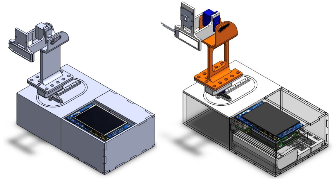
Fig. 11: Original and final CAD iteration respectively
As for circuitry, we wanted one switch to turn on the backlight LED and servos for a smoother user interaction. We began with the 6V battery pack we were provided with in class. However, that much voltage is too high for the backlight LED which is rated for 3V. Also, since we wanted a smooth rotation for the servos, at 6V they would rotate too fast. Next, we decided to use a 2-AA battery pack that provided us with 3V. This worked well for the backlight LED, but not for the servos. We noticed that the servos would jitter with this battery pack. Two of the main electrical reasons that this happened was that the current draw from them was too high, and that the battery pack was not a constant power source. Finally, after going through RPi forums, we stumbled upon a recommendation to try lithium ion batteries which can withstand the high current draw. We were also recommended to try a more accurate Pulse Width Modulation (PWM) signal. We achieved this by using the PigPio library available with Python. Its unique feature is that it times GPIO events at source which makes timing accurate since servos work on microseconds. The 3.7V and PigPio implementation got rid of all servo jitters we were having
Result
A video of Luxor the III in action and still photos are shown below:
Demonstration Video
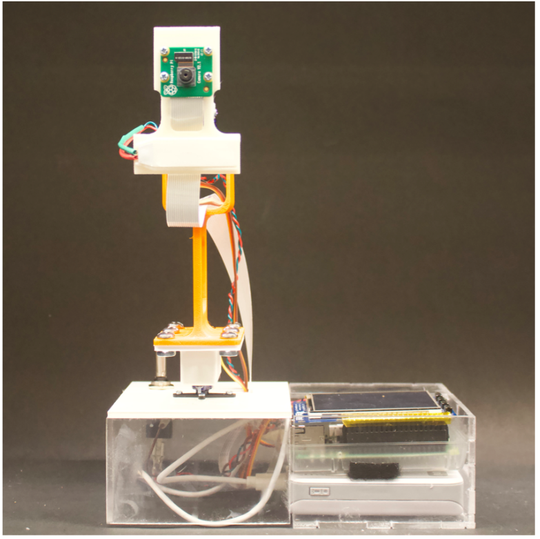
Fig. 12 Front: Front view of Luxor the III with top and bottom servo at center
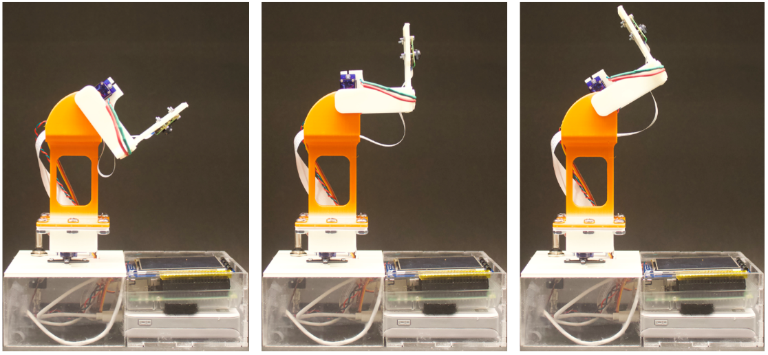
Fig. 13 Front Rotated: Front view of Luxor the III with bottom servo at +90-degree limit and top servo going from negative to positive limit
Conclusion
Overall, we are content with the outcome of our project. We successfully built a Pixar inspired lamp that can track an object with an Aruco marker and have a smooth user interaction. The two main aspects that we struggled with the most were getting the OpenCV and Aruco marker recognition to work, and integration of various states our project had. The main challenges with OpenCV and Aruco marker recognition were running out of space on the SD card and having to download various supplementary packages. Finally, to ease our code integration, we split our code into one main function that contains sub-functions that are called when necessary.
Future Work
Given more time and a bigger budget, we would’ve further iterate the body to avoid any shaking when the servos rotate. Also, implementing a Proportional Integral Derivative (PID) controller would have given us a more accurate object center. Finally, adding a third degree of freedom by adding another servo would allow for a more interactive application.
References
Acknowledgments
A huge thank you to Professor Skovira and the Teaching Assistants throughout the whole semester and this project. They helped us with various aspects of software and hardware issues, such as Pi Camera and PiTFT clicking. For both of us this has been our favorite class in the four and a half years we have spent at Cornell. We were able to demonstrate and improve our electromechanical design skills, and we encourage everyone to take this class.
Contact

Diego Horna
dh468@cornell.edu
LinkedInDiego was in charge of the Solidworks design and assembly, circuitry, GUI, and arm dynamics.

Deepthi Krovvidi
dk562@cornell.edu
LinkedInDeepthi was in charge of setting up OpenCV, recognizing and getting centers of Aruco markers with the Picamera, and the servo sweeping and tracking functions.