Raspberry Pi Theremin
William Abajian and Stephen Schneider
Introduction
In this project, a Raspberry Pi Theremin was successfully built. After some troubleshooting with using the Raspbery Pi Camera to analyze real-time video footage in Python, a hand detection python script was successfully implemented to detect the area of a hand placed over the camera. This was manually tested for accuracy before implementation. After realizing that the Raspberry Pi built-in DAC could be accessed with a C program, more trouble came when attempting to use a socket to speed up the communication between Python and C for real-time processing of the hand detection algorithm. After going through many different types of sockets, we found ZMQ, which allowed for low latency communication. Once this was completed, implementing the various waveforms and assigning effects to the potentiometers connected to the Pi was not difficult. The waveforms were tested as they were made to determine if varying sounds were made by them. The last difficult procedure was implementing the delay effect which required a higher understanding of the C program that was used to output audio. The final tests of the whole device was simply using it, as the sounds created would be indicative of correct results.
Objective
Our goal for this project was to create a synthesizer which would use a hand-detecting CV algorithm to determine the frequency which would be outputted. In addition to this, we wanted to have an array of hardware inputs, including push-buttons, switches, slides and knobs, to further control the creation and output of the sounds created. Finally, we wanted all of this to fit into a neat and tidy housing.
Design
Using Raspberry Pi Camera with PiCamera
Upon connecting the Raspberry Pi Camera to the built-in camera port with the blue area pointed towards the Ethernet port, the camera was configured manually on the Pi. After rebooting the Pi, the camera could be used. In order to successfully implement real-time video processing into a Python script, we made use of the picamera module for Python. We knew to do this (and how) from the helpful tutorial given on pyimagesearch.com (see References under “Picamera implementation”). We will refer to the script obtained on this website as the “picamera script”.
During the first week of our project, the Python script we were using could not process the video without serious lag. Our frame-rate was about 11 FPS at best and we needed somewhere around 30 FPS. After asking around for help, we discovered that it wasn’t the Python script or the camera at fault. It was version incompatibility between the Python script and the picamera module necessary to process video into Python. The program we were using could only work with a previous version of the picamera module. To solve this problem we uninstalled our version of picamera and installed the previous version using the command ‘sudo pip install picamera == 1.10’. The Python script we used was then able to process video very quickly (~28 FPS) and we could move on to the next phase of our project, utilizing a hand detection algorithm.
Hand Detection Algorithm
Finding a hand detection algorithm that worked regardless of the background was very time consuming. Luckily, we were able to take advantage of the OpenCV open source computer vision Python library after installing it onto our Raspberry Pi. This was done using the command ‘sudo apt-get install python-opencv’. The Python library “Numpy” was also installed using the command ‘sudo apt-get install python-numpy’. Numpy is useful for quickly calculating the complex operations necessary for image processing. Although we could make use of these valuable resources, many of the available open-source algorithms online were not robust enough to detect the hand if the background was inconsistent.
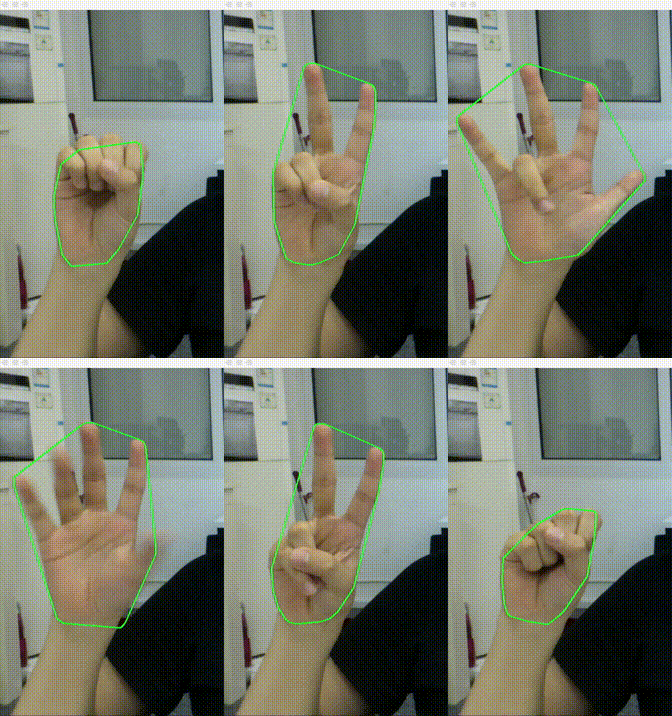
An initial attempt to program our own algorithm using OpenCV to detect motion was attempted but failed since the functions used took too long to implement. After conducting more research, a Python script was finally found that was able to detect the hand reliably and smoothly. This script was found on Github (see References under “Hand detection script”). The algorithm took advantage of the unique color of skin to detect the hand by searching for a narrow range of color pixels. Once detecting pixels in this range, a morphological opening and closing was done using a 5x5 sized kernel to remove noise (especially background noise) in the detected skin region. Contour detection was used to segment this region so that the resulting boundary could be mapped out to a rectangle (the largest rectangle that was able to fit into this region). The width and height of this rectangle was used to calculate the area of the hand which was the value used to control the frequency which was output from the Theremin. The area value was output to a C program using a socket. This procedure will be described in later sections. This script was then implemented into the aforementioned picamera script. The final script can be seen in our code appendix under “hand_posture.py”.

Credit to RainYear
Generating Sound
Of course, one of the most important parts of this project was the ability to make sounds. We decided that Direct Digital Synthesis would be the most flexible way to create these sounds. Instead of calculating the wave values on the fly, we constructed tables of values, 1024 wide with 16 bits of resolution, to store the values. These tables were created in Excel, and we made waves for sinewaves, square waves, triangle waves, and reverse saw waves, the latter three of which were made using the Fourier series approximation of each to sound better. Each of these waves had several tables for them, with differing amounts of harmonics, for different sounds. The sinewave harmonics were created by adding sinewaves that have half the amplitude and double the frequency of the previous wave. 5 harmonics were created using this method. Final sinewaves were normalized to all have an amplitude of 32765, the necessary wave amplitude for clean Raspberry Pi digital to analog sound output. An example of three sinewaves in summation after normalization can be seen below:
Square wave harmonics of 2,3,5,7 and 9 were implemented using the following Fourier series function (From Wikipedia):
An example of the 2nd and 7th harmonic of the square wave after normalization can be seen below:
The first five harmonics of the triangle wave and the 1,2,3,6, and 10th harmonics of the reverse sawtooth wave (both also normalized to have an amplitude of 32765) were also implemented in our theremin harmonic selector.
The Fourier series equations used to construct these waveforms are below (From Wikipedia):
Once we had tables of sounds to output, we needed to figure out how to actually output them. After some early research, it seemed that the Raspberry Pi did not have an onboard DAC, or at least not one available to us. So, we got an I2C 12-bit DAC, the MCP4725, to hook up to the Raspberry Pi. After interfacing with this device using some demo code provided by Sparkfun here. Quickly in testing we found that I2C was too slow, even after maxing out the clockspeed. Next, we asked Bruce Land for some assistance, and he suggested an SPI DAC, called the MCP4822. Using example code from the same previous link, we were able to communicate with this DAC, but even at full speed we could not get it as fast as we needed, and audio was clicky and laggy.
Back to the drawing board, we decided more in depth research was needed. We found that there was some examples code already on the Raspberry Pi, located at /opt/vc/src/hello_pi/hello_audio , which would output a simple sinewave on the audio port. This piece of code would buffer the values just ahead of time before playing them, meaning that any sort of hick-ups or short context switches wouldn’t interrupt the playback. We jumped on this code and used it as our template for making our sounds work.
Interfacing with Buttons, Switches, Knobs and Sliders
In order to interface with the knobs and sliders we purchased to control various aspects of our sound synthesis, we needed an ADC to convert the voltage values at the center terminals to digital values. Just like with the lack of DAC, the Raspberry Pi also lacks an onboard ADC. Thus, we purchased an MCP3008, a 12-bit, 8 channel ADC with SPI interface. Using what we had learned from the example code from sparkfun, as well as the data sheet for the MCP3008, we used the wiringPI SPI library to communicate with the ADC. This communication required various steps, which we learned from the datasheet. First, a 1 had to be sent to the ADC to prepare it to receive a command, with which it would reply back with a byte full of 0s. Then, a command had to be sent, which was made up of the channel needed concatenated with XXXXX, so that way the3 channel bits would be at the front, which we used 10000. So, for example, to read channel 3, first we sent 0x01, then we sent 0xB0, and would receive first 0x00, then the upper 2 bits of the input analog value, and then the lower 8 bits of the analog value. In this way, we could read the position of the knobs and sliders.
For the buttons and switches, we simply used external pullup resistors and read the values with wiringPi. This involved placing a 1kOhm resistor between our Raspberry Pi port and the switch, then a 10kOhm resistor from Vdd to the 1kOhm resistor and the switch, and then the other side of the switch to ground. This meant that the input would be held high, until the switch was flipped, at which time it would go low. In this way, we could read the position of the buttons and switches.
Putting It All Together
Our first challenge of integrating all these parts (the CV algorithm, the DDS algorithm, and the readings from various knobs, switches, buttons, and sliders) was to have some sort of Inter-Process Communication. This was because we wrote our CV algorithm in Python, and our DDS algorithm in C, so we could not just put one inside the other. Plus having them in separate processes meant they could run concurrently on separate cores. Our first method of making this communication possible was to use Unix Domain Sockets. These sockets are built for IPC, and never leave the computer on which they are running. Unfortunately, we found these to be too latency intensive, especially when blocking, and made our audio sound very clicky, due to periods of waiting for packets. To fix this, we turned ZeroMQ, a distributed messaging library built for hi-speed messaging in a tiny package. Using the push-pull socket types, we got very quick communication from the CV program to the DDS program with no discernable latency causing audio glitches. We followed this guide. The value we passed through the socket was the area of the hand, as determined by the CV algorithm.
With the two processes now communicating, it was time to finalize the design. Our DDS algorithm, between each period generated and buffered, would poll each of our inputs, including reading a packet from the ZMQ socket. These inputs would be assigned to their respective flags or value variables, which would then be used when generating the waves to be outputted. These are the following settings we implemented:
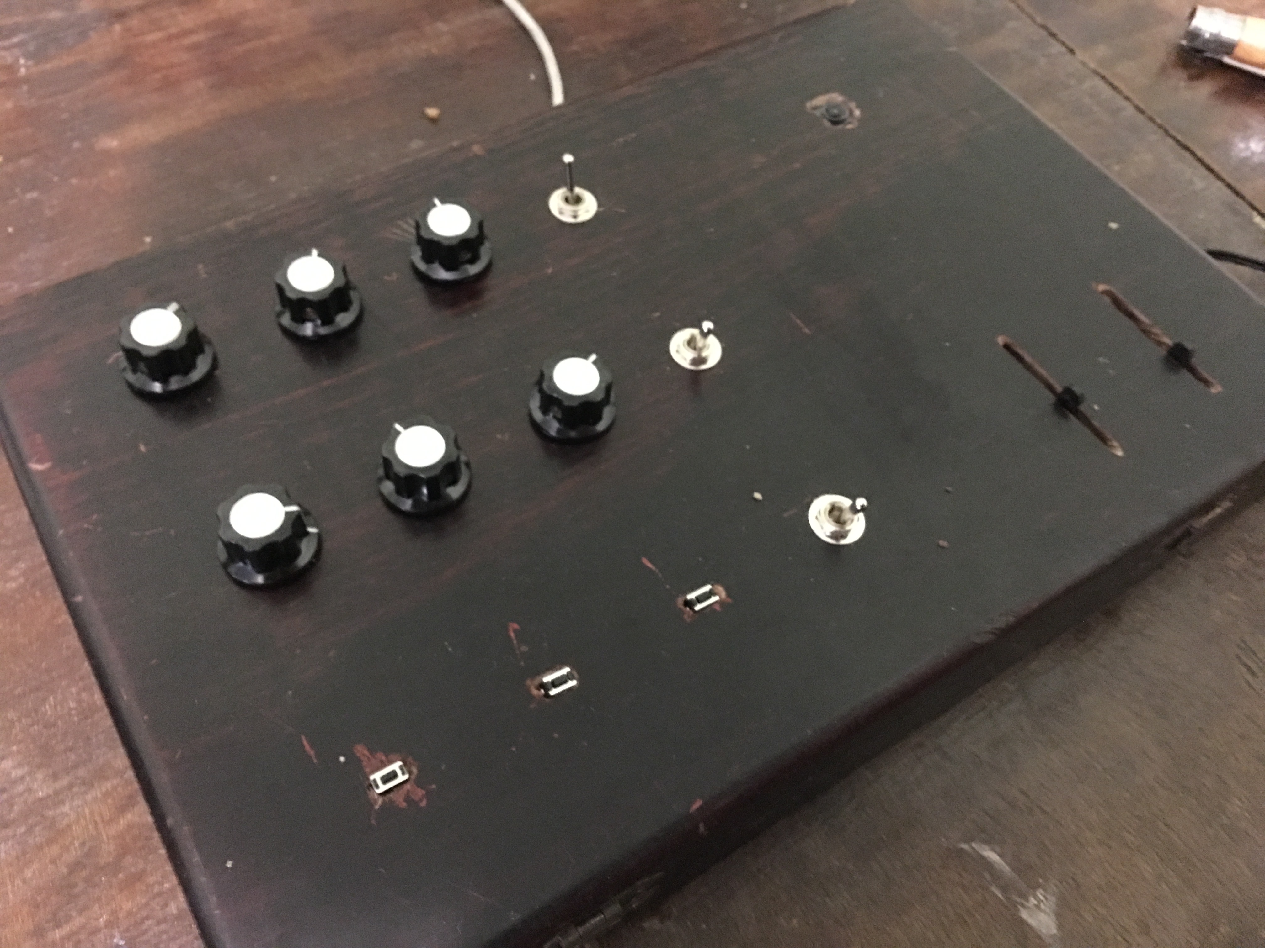
Frequency: The frequency of our waves could be governed by two things: Either the knob in the upper right hand corner, which would increase frequency as the knob was turned to the right, or the input from the CV algorithm, which would increase frequency as the area of the hand read was increased. This value of frequency was stored in an integer known as “inc”, which was the value used to increment the pointer pointing into the relevant waveform array, thus a higher inc would be a higher frequency as it would move through the array faster. The decision on which output to use was dictated by our top switch, with the upper position using the CV algorithm and the lower using the knob.
Easy mode: We developed a feature we called easy mode, which when activated (by switching the middle switch down) would bin the inc value made by the above algorithm into a G major scale, making only those notes possible to play. This was done by constructing an array of each note in the G major scale in the range of frequencies we could play, and search through this array, determining which note the current frequency was just below, and then replacing the current frequency with the found frequency. In this way, it was a lot easier to play actual songs, as can be seen below:
Shape and Harmonics: As mentioned above, we had built different arrays for different shapes, each with different arrays for the number of harmonics used to build those particular waves. We selected between these with 2 different knobs, one for shape and one for harmonics. We used only the top 2 bits of each of these inputs so we would only have 4 settings for each, for a total of 16 different waves. Then, we used nested switch statements to actually put these waves into use, switching based on our inputs from the ADC.
Delay: One feature we had wanted from the beginning was delay, where the sounds we played would echo back. Our settings for this were controlled by two knobs, one with number of delay samples taken, so whether there was no delay, or one delay sample to be replayed later, or two delay samples, for one to be replayed then the second replayed again twice as long after, or three. Then, we controlled how quickly these would playback with another knob we called delay frequency, which would control the space between the current playback and each successive buffered delay. We achieved this by creating an array of 3 arrays, each of these arrays in which we would store the current value of the analog output, and then output the next value in the array, as we used it as a cyclic array, with the pointer to the current entry wrapping around based on the set frequency of the delay frequency knob. Initially, we had a problem where the program would crash if we put on all the delays at the lowest frequency, but we discovered that the array simply wasn’t long enough and we were indexing outside of it, so we calculated the requirement and made that the length, fixing the problem.
Modulation: One thing that was in the original audio.c example file we used to do the DDS was that the waves would actually vary in frequency over time. We decided this modulation was kind of cool, so we mapped the right button to turn it on when it was held down. This would then work by defining a secondary frequency with the bottom right knob, and when the button was pressed, the frequency outputted would move up and down between the frequency being play by either the CV algorithm or the frequency knob in the upper right, and the frequency set by the knob on the bottom left. When programming this feature we had a strange glitch where if we would allow the frequency to reset to the one specified by the normal playing algorithms, it would sound very distorted and just keep rising in frequency. We decided to turn this glitch into a feature, and had it controlled by the bottom switch, switching between normal modulation and “overdrive” modulation with it.
Attack: In order to actually play songs, we had to be able to control whether or not sound was actually being created and outputted. To do this we made the middle button the attack button, which when pressed (or not pressed, we could switch this depending on how we wanted it to work in the code), the playback would stop (besides the delays that needed to be played at that time), and when released (or pressed) would begin playback again. This can be seen used in the video above to play “Mary had a Little Lamb”
Power Down: While the Pi could be turned on by simply plugging it in, we could not shut it down by just unplugging it, as this overtime damages the SD card. So we made the left most button, when pressed, make a call to the terminal to turn off the Pi, using sudo shutdown -h now.
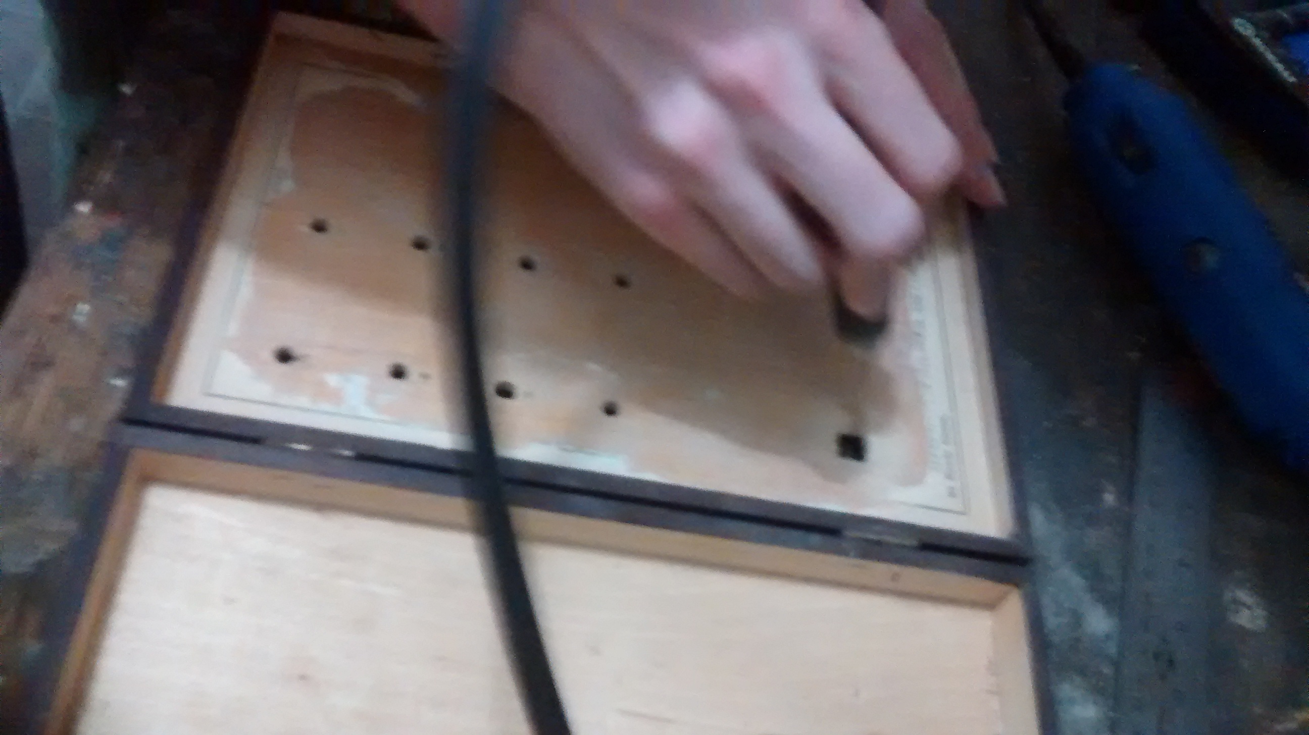
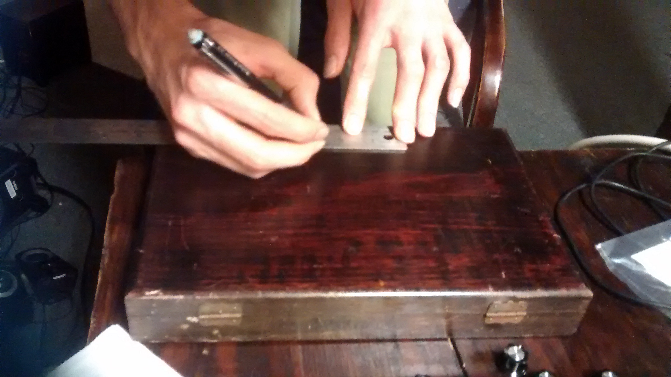
Housing


Results
Our finished product was able to detect hand area successfully and continuously as the hand moved up and down above the camera. We knew this since the sound output from the theremin was continuous and in synch with the moving hand. The added function which assigned specific hand areas with discrete tones could be activated by a switch. This also worked very smoothly as you can see in the video posted. The wave shape and harmonic varying potentiometers worked well and each had very distinct sounds. The delay effects produced from both of the delay knobs had surprisingly good quality. A special feature that made two sounds (another switch was used to alternate between these sounds) similar to “wowow” sounded very cool as you can hear in the video. A switch added that transferred the device from a theremin to a synthesizer (controlling frequency by a potentiometer) made frequency control a bit easier since it didn’t require as much practice to implement. The button added to stop all sound was beneficial for making songs that required distinct notes and rhythmical patterns. Both the octave and volume slide potentiometer functioned appropriately and were very easy to use. Finally, the shutdown button added was useful so you don’t have to shutdown the Raspberry Pi by unplugging it which can be damaging to the system.
Conclusion
One major conclusion we learned from completing our project was that it is difficult to use the latest version of the Python Picamera module with the current methods of processing video frames into Python from the Raspberry Pi camera. Downgrading to the previous version may be necessary. Another conclusion is that a socket can be very useful when attempting to move data from a Python script to a C program in real-time. We also learned that you can utilize the Raspberry Pi’s built-in DAC by altering the script “audio.c” located in the directory ‘/opt/vc/src/hello_pi/hello_audio’. This can be useful when attempting to perform audio synthesis. It was also valuable to understand that waveforms do not need to be calculated in real-time if they are made into arrays which are stored on the Pi. Given this knowledge, one can explore the endless landscape of digital audio synthesis!
Future Work
If we were allowed more time to work on this project there are a number of features we could add to our device. Due to the infinite amount of waveforms that we could potentially generate, we could design our own effects and try to implement more of our favorite, including a phaser, tremolo, vibrato, fuzz, a looper pedal and distortion. Another option would be to program one of our potentiometer knobs to be able to adjust the sensitivity of the computer vision algorithm. We could also design the theremin to produce chords rather than single tones. In addition, with all these added features it may be necessary to pursue latency reducing methods, in which case we would explore using isolcpus and taskset to relegate the two processes to their own CPUs.
Cost Analysis
| Item | Price | Quantity | Total (Tabulated) Cost |
|---|---|---|---|
| Raspberry Pi 3 Model B | $35 | 1 | $0 |
| Pi Cobbler Plus | $6.95 | 1 | $0 |
| Raspberry Pi Camera | $24.50 | 1 | $24.50 |
| Wooden Microscope Slidebox | Free | 1 | $6.99 |
| MCP3008 ADC | $2.19 | 1 | $2.19 |
| 10k Slide Potentiometer | $1.50 | 2 | $3.00 |
| 10k Rotary Potentiometer | $0.76 | 6 | $4.56 |
| Knobs | $0.875 | 6 | $5.25 |
| Push Button (from lab) | Free | 3 | $0 |
| Toggle Switch | $1.92 | 3 | $5.76 |
| Headphone wire | $3.13 | 1 | $3.13 |
| Headphone Jack | $1.74 | 1 | $1.74 |
| Wires and Resistors (from lab) | Free | N/A | $0 |
| Total | $57.12 |
Division of Labor
Stephen was responsible for getting the hand detection to work with the Raspberry Pi camera. He did this using open source Python code referenced below. After completing this task he also soldered all of the potentiometers to the device. Stephen also made excel tables for each of the waveforms that were then implemented in the audio.c program.
Code Appendix
audio.c//The DDS Algorithm and Input Wrangler
hand_posture.py//The CV Hand Detection Algorithm
References
Acknowl-
edgments
We thank Professor Skovira for his assistance when we hit a dead end with the Raspberry Pi camera module, as well as Dr. Bruce Land for providing us with the SPI DACs we tried using. We are also grateful to be allowed the workspace provided by Cornell University. We also would like to thank our class peers who helped us solve our problem with downgrading picamera as well as TA Jingyao for his assistance with this problem.
Contact
William Abajian: wpa26@cornell.edu
Stephen Schneider: sms675@cornell.edu