ECE 5725 Final Project
Robot Dog
Zhuo Chen zc292, Rui Min rm877
Dec. 2016
Introduction
In this project, we have built a robot dog based on Raspberry Pi. First, this little dog can find your face and follow your steps. This function is mainly achieved by detecting the user’s face and use the position and size information to control the motors. Second, this dog can recognize a “go” command which is a person’s “go” word and a “stop command” which is the sound of a whistle and make the corresponding response. This is achieved by detecting the sound with zero crossing frequency detection. Third, this dog can make various sounds when it cannot find the face, or reply to “go” and “stop” command.
Objective
Build a robot dog with following functions:
[1] Face detection
[2] Move and track user's face
[3] Simple voice recognition of two commands
[4] Make sound response
Design & Testing
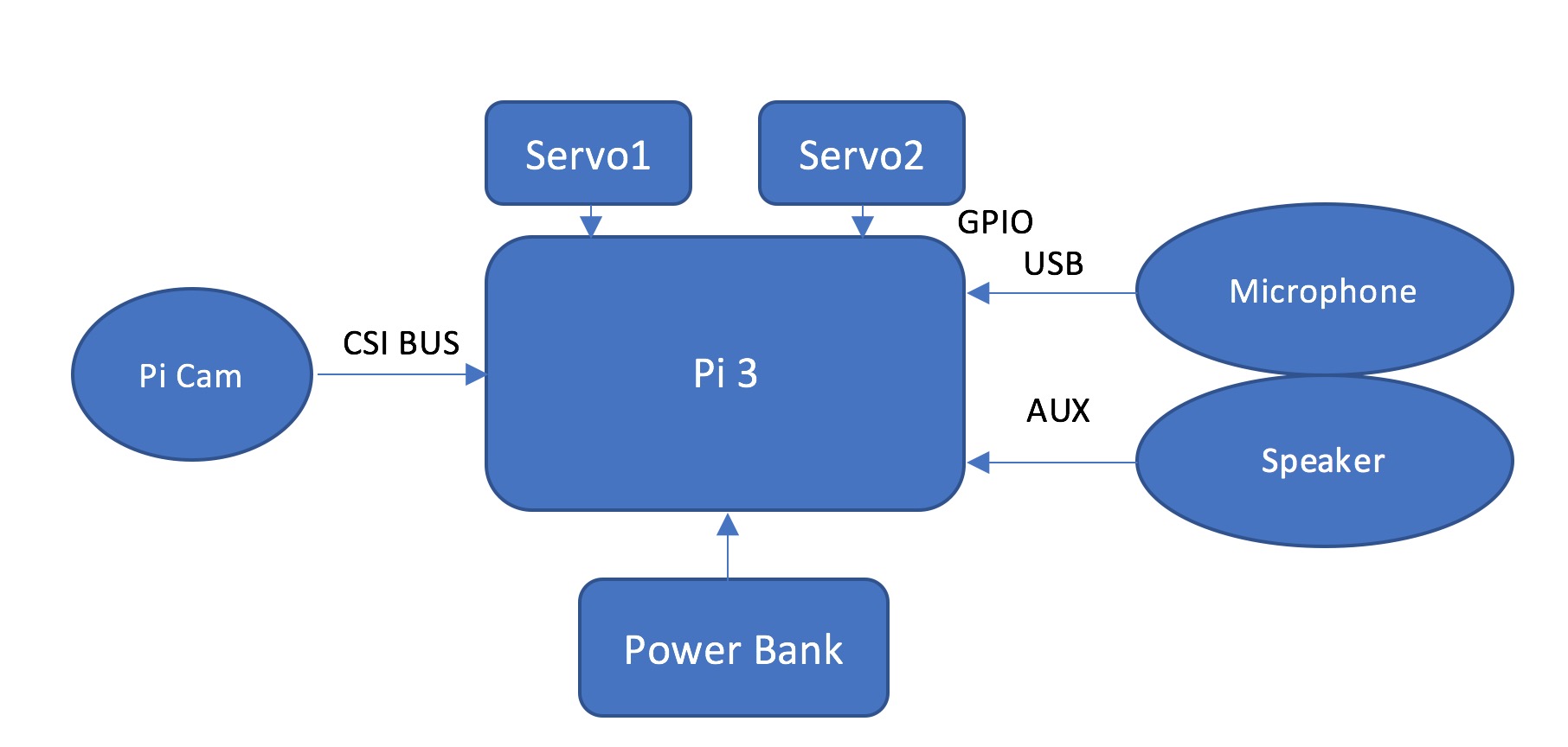
System Setup
1. Pi Camera and mount
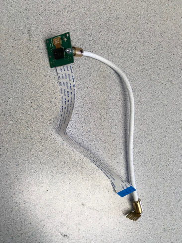
In the final system setup, we use the Pi Camera and a mount we bought from Amazon. The Pi Camera is connected to Pi via the dedicated connector. After turning on the enable camera option in the configuration and reboot, the Pi camera was ready to use.
The official user manual suggests that the mount should be plug into the USB of the Raspberry Pi. However, the camera will shake together with the Pi when the robot dog moves. The Pi is mounted on the robot frame with VELCRO tape, not stable enough for the camera. As the camera shakes, the image will be blurred, leading to a low performance of the face detector. Thus, we fixed the mount on base of the robot frame and the performance of the face detection has been improved.
2. Microphone
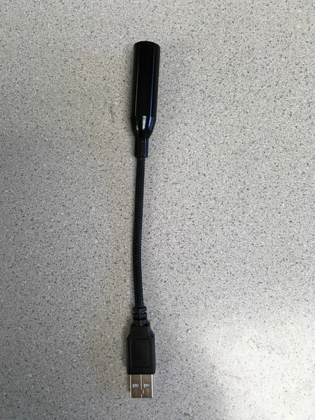
The installation of the Microphone is as simple as plugging it into the USB.
3. Robot frame
The robot frame used for this project is same one we used in Lab 3. For detailed installation procedure, please refer to the Lab 3 Instruction Note[6].
4. Installation of OpenCV
We followed Adrian Rosebrock’s tutorial to install OpenCV 3.1.0 on the system [7]. The installing process can be summarized as downloading source code, installing dependency, compile and install. One thing to point out is that we did not install the OpenCV in a python virtual environment. Python virtual environment is a useful tool to isolate developing environment. However, we use this Raspberry Pi dedicatedly for this project. Thus there’s no need to install the OpenCV in a python virtual environment.
5. Installation of pyAudio
We followed an online tutorial to install pyAudio on the system [8] as:
$ sudo apt-get install git
$ git clone http://people.csail.mit.edu/hubert/git/pyaudio.git
$ sudo apt-get install libportaudio0 libportaudio2 libportaudiocpp0 portaudio19-dev
$ sudo apt-get python-dev
$ sudo python pyaudio/setup.py install
6. Motors
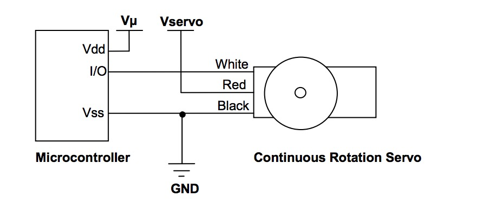
We use two servo motors for the two wheels. They are connected to Pi via Pin 20 and 21 (BCM number). These motors are powered with dedicated batteries with a separate power switch. The ground is shared with Pi as Figure 3 shows.
Face Detection
1. Face Detector
The face detection function is mainly achieved by the face detector module of OpenCV. There are generally two algorithms for this purpose. Namely Haar Cascade and Local Binary Patterns (LBP). Haar Cascade is used for this project because it has a higher detection accuracy. LBP has a faster processing speed but less accuracy. A faster algorithm means we can process more frames in a unit time, resulting a faster frame rate. However, the frame rate requirement is not very high for this project. Detect a face in the frame accurately is more important for this project. Thus, Haar Cascade is finally chosen.
A face detector instance can be setup by code[5]:
facedetector = cv2.CascadeClassifier(cascade_path)
where the cascade_path is the file path of the face cascade xml file. A grey scale image will be passed into the detector and the position, width and height will be returned. The center of the face can be determined with this information.
2. Frame Capturing
The face detection function will serve as the navigator of the system. The position of the user will be detected in the camera frame and relative position will be returned. The robot will move regarding this relative position.
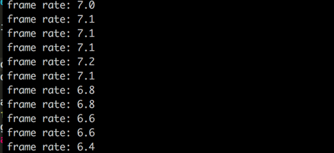
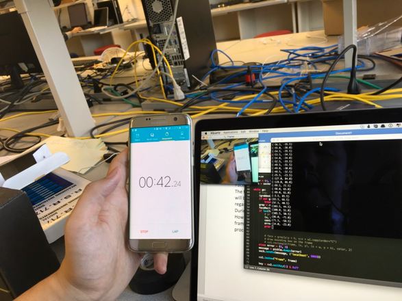
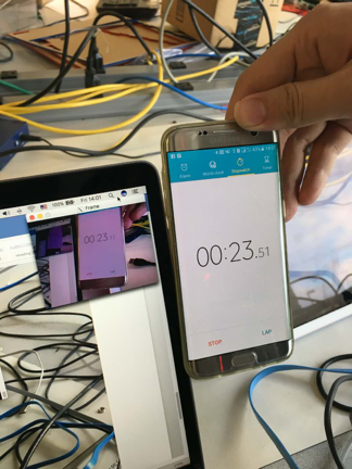
During the first phase of development, the camera used is the Logitech C525 USB webcam. However, the frame rate is only about 7 fps, which means this system could only process 5 frames per second and return the relative positions. This could be adequate for navigation purpose. However, there is a lag around 1s as Figure 4 shows, this will affect the navigation fatally. The latency was measured by comparing the taking a picture of the stop watch directly and together with the image preview of the processed frame.
As one of the TA, Jingyao suggest, we can make use the 4 cores of the Raspberry Pi 3 to process the frames in parallel. The latency may be reduced by a faster processing speed.
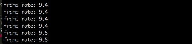
The program then edited to work with multi processes. The frame rate was increased to around 9 fps, which is 2 fps faster than single process version. However, the latency was getting worse with multi processes as Figure 7 shows. The latency was increased to 4s, it may cause by the overhead introduced by the multi processes.

The tests above indicated that the latency was cause by the procedures before detecting the faces in the frames, which leaves the image capturing process most suspicious. Besides USB webcam, the most popular camera solution on Raspberry Pi platform is the Pi Camera, which is designed dedicated for Raspberry Pis. The Pi camera is connected with the Pi with a dedicated connector, this may lead to a faster operation speed.
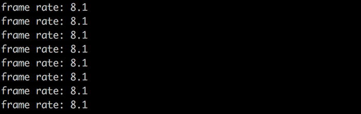
After switching to Pi camera, there was no improvement on frame rate. However, the delay was almost eliminated. The delay now is around 0.3s, which could be enough for tracking slow movement of the face.
3. Position interpretation
The relative position between the robot and user is read by the camera. Two ways of interpretation the position signal were tested during the development.
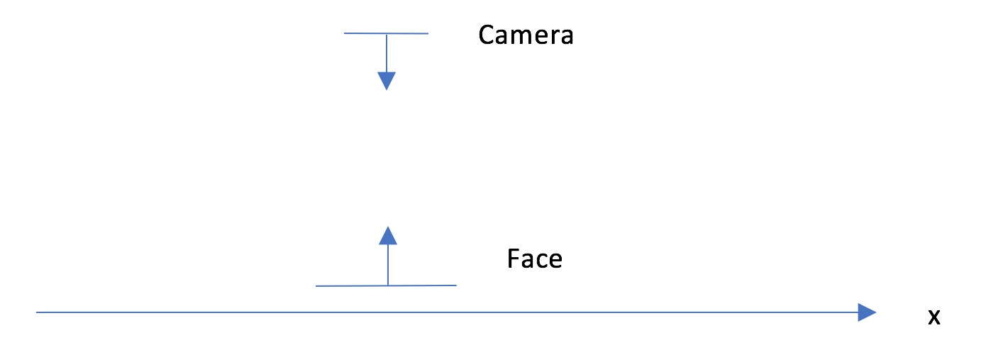
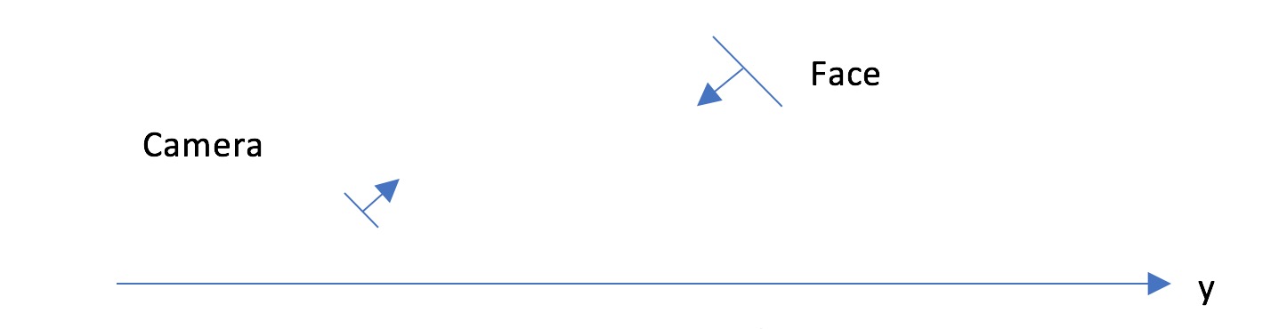
If the user stand straight and look down at the robot, the position can be simply interoperated x and y value.
However, during the development, some problems occurred with this method. First, moving towards and backwards to the robot did not lead to much change in y direction. This can be solved by adjusting the gain when translating the error signal to movement adjustment signal. A more serious problem with this method is that, when the user stand straight, the size of the face in the frame will be small. A small face size will lead to a degrade accuracy and more computing time. Besides, as the camera is tilting towards the light on the ceiling. If there is high intensive light source in the image, the Pi camera will lower the exposure rate, leading to a dark image and the face cannot be found by the face detection algorithm. We have tried to turn off the auto exposure adjustment, but it is hard find a good manual value for this application. During the testing, the system frequently report failed to detect the face.
Instead of using the y axis value, another method we proposed to represent the distance of the face to the camera is the size of the detected face.
After obtain the position of the face in the frame, an error signal will be generated to control the motor. The x-axis error is the deviation of the detected face positon from 0, which is the central position. The size error is the deviation of the detected face size from 55, which was selected after testing a set of values. If the central size is too small, the robot will stop too far away from the user. Also, this will make the user’s face hard to be detected by the face detector. If the central value is too large, the robot will stop close to the user. However, during the testing it was found that when the robot stop too close to the user, the face would be out of the frame. 55 was the best value found.
This method was tested and the system showed a right response to the change of the face position.

Figure 12 is the testing result of the position interpretation function. When the tester’s face in the left or right side of the frame, the error message was changed regarding to the position.
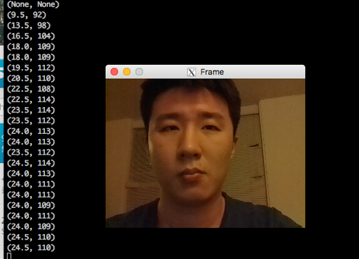
Comparing with Figure 12, the tester’s face was closer to the camera. The size error changed for around 70 to around 110, which was same as expected.
4. Sending the error signal
The error signal need to be send to the main program of the system to control the wheels. The signal is send with a UDP socket. In the later section, it will be mentioned that the system involved two functions need to send instruction to the main program. Instead setting up another socket, the two set of instruction are differentiated by a ‘name tag’. The structure of the signal is:

The first element of the signal tuple is the name tag, which indicate this is the error signal. The second element is the error signal itself, which is a tuple containing the x-axis error and the size error. If no face was found, the error signal will be (None, None). The message is serialized with python pickle before sending.
This part of design refers to ‘face_m_picam.py’ code.
Movement control
1. Motor control model
In Lab 3, our group has already implemented the motor controller class. The class used for this project was an edited version of the Lab 3 code. According to the servo datasheet[3], “As the length of the pulse decreases from 1.5 ms, the servo will gradually rotate faster in the clockwise direction” and “Likewise, as the length of the pulse increases from 1.5 ms, the servo will gradually rotate faster in the counter-clockwise direction”. The length of period is base pulse(1.5ms) plus the adjusted pulse. The range of pulse is from 1.3ms to 1.7ms and we have 21 stages ([-10, 10]).
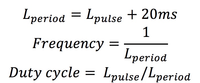
where L_pulse is the calculated pulse width regarding to the speed stage.
This set of code has been tested during Lab 3. However, when it was running with the Face recognition code, the wheels started to shaking, even the speed given was 0. In Lab 3, the motors were driven by PWM model for RPI.GPIO, which is a software PWM. When this program running with other processes, the control of PWM wave may be delayed and loss accuracy, leading to the shaking wheels. The course instructor suggested us using pigpio model, which is already built-in the Raspberry Pi. There are two options using PWM with pigpio. The first one is using the hardware PWM model. There are 2 hardware PWM models on Raspberry Pi 3, which can be accessed via pin 13 and 18 (BCM number) with code [4]:
hardware_PWM(gpio, PWMfreq, PWMduty)
However, as it was mentioned in the lecture, using the two hardware PWM models will have conflict with the audio out function of the Raspberry Pi. Instead of using the hardware PWM models on Raspberry Pi, we used the hardware timed PWM, which is accessible from all the GPIOs. This method involved the DMA model on the Raspberry Pi and the performance will not be affected by the CPU workload as the software PWM.
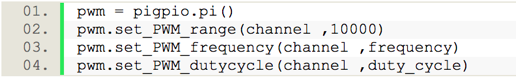
The first line connected to the pigpio demon, which should be started in the terminal before running any pigpio involved program with command:
sudo pigpiod
The second line changed the default range of a full PWM cycle from 255 to 10000 to increase the control precision. For example, now a 10% duty cycle is 1000 rather than 26. The last two lines change the frequency and duty cycle to the expected values.
After switching to pigpio library, the two wheels now have a stable performance.
2. Converting error signal to motor control signal
Making the wheels to move with the face movement in x-axis (refer to Figure 10) can be achieved by controlling the wheels move at different direction (forward/backward) with a certain speed.
At first, we designed a schema that the speed of the wheels should be proportional to the error signal value as:

However, if the gain is too high, the control process would overshoot. The frame rate of the face detection process is not high enough to counter with the fast change frames. As we only expect the system to track low speed moving face, we simplify the x-axis control schema to:

The new schema was tested and has a satisfying result.
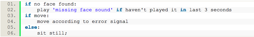
For y-axis with size as error signal, the proportional control worked fine. The control signal for x-axis and y-axis If there is no face detected and the error signal is (None, None), the system will simply sit still.
This part of design refers to motor_control_pigpio.py, wheel.py, car.py.
Voice Recognition
The zero-crossing rate is the rate of sign-changes along a signal, i.e., the rate at which the signal changes from positive to negative or back.[1] This feature has been used heavily in both speech recognition and music information retrieval, being a key feature to classify percussive sounds.[1]
ZCR is defined formally as

Where s is a signal of length T and 1R is an indicator function.
In this project, we use a zero crossing method to calculate the fundamental frequency of a voice.[2]
Since all we needed to do was distinguish two different voices, we used a voice of low frequency and a voice of high frequency in order to have a high level of accuracy. In this project, we used a voice of word "Go" whose fundamental frequency was below 500 Hz to give a move command and a voice of whistle whose fundamental frequency was above 2000 Hz to give a stop command.
In our voice recognition program, we had two thresholds. If the fundamental frequency of the voice was higher than 2000 Hz, we treated the voice as a voice of whistle and sent a stop command through socket. If the frequency was less than 500 Hz, we sent a move command through socket.
One thing we need to point out is that the zero crossing method is easily affected by the noise which means that sometimes the robot will mistakenly recognize the noise, for instance, the voice produced by itself (the robot plays a audio of dog barking when it receives a command ) or the voice by other people. As a result, it needs a relatively testing environment and the amplituderesponse audio played by itself must be low.
Before we tested the voice recognition program on the Pi, we first tested the voice recognition on our own computer, using the internal microphone of your PC. And before we tested the program using a real sound, we first tested it by using specific sin waveforms produced by a waveform generator. In this part, the voice recognition works well, the difference between the recognition value and the real value was less than 30 Hz if the amplitude was large enough.
Then we put the voice recognition program onto the Pi and tested on Pi. In this part, several problems occurred. The first one was that we needed to do some configurations on the Pi for some specific libraries we used in the voice recognition program.
The second problem we faced with was that there was a frame overflow in the Pi. The cause of this problem was that the original frame size (1024 points) we set before was too small. In order to solve this, we increased the frame size to 8192.
The third problem we found was that when power source of the microphone was low, there would be a degradation of performance. After we recharged the power bank, the microphone recovered to its normal performance.
The fourth bug of the voice recognition was that if our voice had a length which was longer than one recognition period we set, the recognition program would send repeated commands. The solution of this was that every time we sent a command, we stored the timestamp. Next time we plan to send a command, we checked the time interval between the current timestamp and the last time stamp. If the interval was larger than 3 seconds, we treated the current recognition as a new one and sent the command. If it is less than 3 seconds, we ignored it.
The fifth point was that since the zero crossing recognition method is a method using an accumulation value, when we recognized a frequency which was below the low threshold, there are two possibilities. One possibility was that this frequency represented a low frequency command and the other one was that it was a signal before a high frequency signal which displayed the beginning of the accumulating process of a high frequency signal. In order to distinguish these two possibilities, after we recognized a low frequency command, we continuously checked the recognized signal after it. If the two signals after it were high, we thought it was the second possibility two and sent the stop command. If not, we could ensure that this was a low frequency command and we sent the go command.
The last problem was that the response voice to the command played by the robot would become a noise and sometimes the robot would mistakenly treated the response sound as a command. Since the voice recognition highly affected by the amplitude of the sound, we decreased the loudness of the response voice to a level which would not influence the normal recognition.
After solving these problems mentioned above, we had a good performance of voice recognition in a reasonable distance ranging from 0 to about 4 meters.
The testing results of this module is shown in Figure 14:
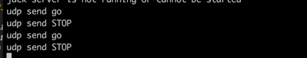
The system responded corrected to the sound commands we generated. Also, the system only responded to one command within 3 seconds as we expected.
This part of design refers to hytersis_fre.py.
Main program
1. Receiving signals
The main program performs as a UDP socket server to receive signals from face and frequency detection modules. The received signal will first be de-serialized with python pickle. Then signal will be processed as the error or command signal indicated by the first element of the tuple. The structure of the tuple could be:
(‘error’, error) or (‘command’, command)
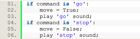
2. Sound Command
As there are only two commands involved, ‘go’(move) and ‘stop’, a Boolean flag will be controlled by these two commands.
The sound playback function used in this project is PyGame mixer. It is initialized with:
pygame.mixer.init()
and playing the sound with:
pygame.mixer.music.load("sound_file")
pygame.mixer.music.play()
The sound files used for this project was downloaded from following sources:
Not find face:
http://www.wavsource.com/snds_2016-11-20_5768273412148964/animals/dog_whine_duke.wav
Go:
http://www.wavsource.com/snds_2016-11-20_5768273412148964/animals/dog_bark4.wav
Stop:
http://www.wavsource.com/snds_2016-11-20_5768273412148964/animals/dog_puppy.wav
3. Movement control with command
The movement control will be affected by the ‘move’ flag. The robot will only move when the flag is true. Also, if no face is detected by the face detection program, the robot will not move.
The part refers to car.py code.
Start and stop script
There are 3 programs involved in this project. A script has been generated to start those 3 programs. Besides, to ensure the pigpio demon starting before running any gpio involved code, the script will start the pigpio demon at the beginning.
The system will keep running unless all the three programs stopped. To stop all the 3 programs, a stop script has been generated. First, the PIDs of the involved processes will be found then kill commands will be sent to each of them. As the motors are controlled by the pgpiod, if the last sent instruction for the programs is not stop, the motors will keep running even the programs has been stopped. Instead of turnning off the gpiod, we wrote a simple python code to send stop command to the gpiod at the end of the script.
This part refers to start, stop and stop_motors.py.
System Testing
For the final testing, we used an iPhone to setup a mobile hotspot and using SSH to connect the Raspberry Pi wirelessly. As the testing of the final system is hard to be demonstrated with data or graphs, the demo video can be served as a good testing process of the system.
Results
The face detection has a decent performance when we changed to detected the distance by face size. The system function well when the tester moved slowly. However, the robot dog will lose track of the face if the tester move rapidly.
The frequency detection module function as we expected when we say ‘go’ or blow the whistle. However, the ‘go’ command sometimes get messed with the surrounding noise as the noise may contain a frequency component which can trigger the frequency detection. The whistle detection worked well as the frequency of the whistle is much higher than the noise.
All the sound has been played correctly with regard to the situation. However, when the volume is high, the ‘dog bark’ may trigger the ‘go’ command. We have to lower the volume of the speaker.
The robot dog can follow the slow-moving tester and respond to the sound command most of the time.
Conclusion
All the planned work and proposed functions has been finished at the end of the project and all the function has been proved to be functional.
Future work
The current system using python version of the OpenCV which has lower efficiency. If switch to C++ version, the system should have a better performance. Also, the Cascade kernel used in this project is a trained version for front face. The robot is put on the ground and the user looks down at the robot. Retrain the kernel with this certain relative position may improve the performance of the system.
For the sound recognition part, this system suffers from the low quality of the USB microphone and varies distance. A handheld commander would solve the problem. Also, as the accuracy of the frequency improved, more commands can be added to the system and it would be more interesting.
Part List
| Name | Source | Cost | Quantity |
|---|---|---|---|
| Raspberry Pi 3 | Amazon | $37.79 | 1 |
| Raspberry Pi Camera | Amazon | $26.55 | 1 |
| USB Microphone | Amazon | $8.99 | 1 |
| Oracle Speaker | Career Fair Gift | Free | 1 |
| Camera Mount | Amazon | $17.95 | 1 |
| Servo Motor | Borrow from lab | Free | 2 |
| Robot Frame | Borrow from lab | Free | 1 |
Division of Labor
| Zhuo Chen | Rui Min |
|---|---|
| Background Research | Background Research |
| Overall Hardware Design | Webpage Design |
| Face Detection | Voice Recognition |
| Servo Motor Control | Servo Motor Control |
| Test and Debugging | Test and Debugging |
| Project Report | Project Report |
References
[1] Gouyon, F., F. Pachet, and O. Delerue. "Classifying percussive sounds: a matter of zero-crossing rate." Proceedings of the COST G-6 Conference on Digital Audio Effects, Verona, Italy. 2000.
[2] Ahhhh...BIU!
http://people.ece.cornell.edu/land/courses/ece4760/FinalProjects/f2012/tg293/tg293/index.html
[3] Parallax Continuous Rotation Servo Motor Datasheet
https://www.parallax.com/sites/default/files/downloads/900-00008-Continuous-Rotation-Servo-Documentation-v2.2.pdf
[4] pigpio hardware PWM example http://abyz.co.uk/rpi/pigpio/python.html#hardware_PWM
[5] Face Detection using Haar Cascades
http://docs.opencv.org/master/d7/d8b/tutorial_py_face_detection.html
[6] ECE 5725 Lab 3 Instruction Note
[7] Install guide: Raspberry Pi 3 + Raspbian Jessie + OpenCV 3 http://www.pyimagesearch.com/2016/04/18/install-guide-raspberry-pi-3-raspbian-jessie-opencv-3/
[8] [Raspberry Pi] Using PyAudio & External Audio Card for Recording http://raspberrypirecipes.blogspot.com/2014/02/raspberry-pi-using-pyaudio-external.html
Code Appendix
###############################################################################
#                                                                             #
# file:    car.py                                            		  		  #
#                                                                             #
# authors: Zhuo Chen  - zc292                                                 #
#          Rui Min - rm877                                                    #
#                                                                             #
# date:    December 1st 2016                                                  #
#                                                                             #
# brief:   Main program of the robot dog. This program will receive commands  #
#		   from the face and frequency detection and move the car according   #
#		   to the signal 													  #
#                                                                             #
###############################################################################
import RPi.GPIO as GPIO
from motor_control_pigpio import pwm_motor
from datetime import datetime
from wheel import Wheel
import socket
import pickle
import time
import pygame
import thread

# The class of the robot dog
class Dog():
	def __init__ (self, left_channel, right_channel):
		self.left_wheel = Wheel('left', left_channel)
		self.right_wheel = Wheel('right', right_channel)


	def move(self, error):
		x_error, y_error = error
		# if no face found and last instruction is (0, 0)
		# do not send any instruction to the motor
		# it was found out during test that repeatly sending 0 to the motor
		# sometimes cause the motor jettering
		if not x_error and not y_error:
			global last_move_instruction
			if last_move_instruction != 0:
				self.left_wheel.forward(0);
				self.right_wheel.forward(0);
				last_move_instruction = 0
			return

		# adjust y speed with regrad to the size error
		y = int(y_error/2)

		# adjust x speed in two speeds
		# large error for stage 2 speed
		# small error for stage 1 speed
		# very small error or no error, stop
		if x_error >= 80:
			x = 2
		elif x_error <= -80:
			x = -2
		elif x_error >= 40:
			x = 1
		elif x_error <= -40:
			x = -1
		elif x_error < 40 or x_error > -40:
			x = 0

		if x != 0 or y != 0:
			# ensure x, y value within [-10, 10]
			left = self.clamp(-x+y)
			right = self.clamp(x+y)

			# apply speed
			self.left_wheel.forward(left);
			self.right_wheel.forward(right);
			last_move_instruction = 1
		else:
			self.left_wheel.forward(0);
			self.right_wheel.forward(0);
			last_move_instruction = 0

	# ensure x, y value within [-10, 10]
	@staticmethod
	def clamp(in_put, uppper_bound = 10, lower_bound = -10):
		if in_put < lower_bound:
			in_put = lower_bound
		elif in_put > uppper_bound:
			in_put = uppper_bound
		return in_put

	# dog barking funtion
	@staticmethod
	def bark(index):
		if index == 'stop':
			pygame.mixer.music.load("sounds/dog_puppy.wav")
		if index == 'missing_face':
			pygame.mixer.music.load("sounds/dog_whine_duke.wav")
		if index == 'go':
			pygame.mixer.music.load("sounds/dog_bark4.wav")
		pygame.mixer.music.play()


if __name__ == '__main__':
	# setup the two channels for the wheels
	LEFT_CHANNEL = 20
	RIGHT_CHANNEL = 21
	GPIO.setmode(GPIO.BCM)
	# initialize a dog instance
	dog = Dog(LEFT_CHANNEL, RIGHT_CHANNEL)
	# setup the socket to receive signal
	sock = socket.socket(socket.AF_INET, socket.SOCK_DGRAM) # UDP
	sock.bind(('localhost', 8089))

	# setup pygame mixer for playing sound
	pygame.mixer.init()
	move = False
	continue_loop = True
	found_face = True
	last_bark = 0
	last_move_instruction = None
	while continue_loop:
		try:
			# pooling date from the socket
			data, addr = sock.recvfrom(1024) # buffer size is 1024 bytes
			# unpickle received data
			data = pickle.loads(data)
			# received error signal
			if data[0] == 'error':
				# if no face found
				if data[1] == (None, None):
					dog.move( (0, 0) )
					if found_face == True:
						found_face = False
						if time.time() - last_bark >= 3:
							dog.bark('missing_face')
							last_bark = time.time()
				# move if move true
				elif move:
					found_face = True
					dog.move(data[1])
				elif not move:
					found_face = True
					dog.move( (0, 0) )

			# if received signal is sound command, change the move value and play sound
			if data[0] == 'command':
				print data[1]
				if data[1] == 'stop':
					move = False
					dog.bark('stop')
				else:
					move = True
					dog.bark('go')
		except KeyboardInterrupt:
			dog.move( (0, 0) )
			continue_loop = False
###############################################################################
#                                                                             #
# file:    face_m_picam.py                                            		  #
#                                                                             #
# authors: Zhuo Chen  - zc292                                                 #
#          Rui Min - rm877                                                    #
#                                                                             #
# date:    December 1st 2016                                                  #
#                                                                             #
# brief:   The face detection code for the Robot dog. This program			  #
# 		   will detect and presented faces and sent the error signal to the   #
# 	       main program											              #
#                                                                             #
###############################################################################
import cv2
import os
import numpy
from imutils import encodings
from time import sleep
import time
import socket
import pickle
import multiprocessing as mp
from picamera.array import PiRGBArray
from picamera import PiCamera

# setup the camera
camera = PiCamera()
camera.resolution = ( 320, 240 )
camera.framerate = 60
rawCapture = PiRGBArray( camera, size=( 320, 240 ) )

# setup the face detector
cascade_path = 'cascades/haarcascade_frontalface_default.xml'
facedetector = cv2.CascadeClassifier(cascade_path)

go = True
total = 0
error = (0, 0)

# setup the socket
sock = socket.socket(socket.AF_INET, socket.SOCK_DGRAM) # UDP

# This function will detect the face in the frame and send the error signal to the main program
def get_face_send(frame):
	try:
		gray = cv2.cvtColor(frame, cv2.COLOR_BGR2GRAY)
		faceRects = facedetector.detectMultiScale(gray, scaleFactor=1.1, minNeighbors=9, minSize=(10, 10))
		if len(faceRects) > 0:
			(x, y, w, h) = max(faceRects, key=lambda b:(b[2] * b[3]))
			center = (x+0.5*w, y+0.5*h)
	 		error = (160-center[0], w-55)
	 	else: error = (None, None)
	 	# print error
		message = pickle.dumps(('error', error))
	 	sock.sendto(message, ('localhost', 8089))
	except KeyboardInterrupt:
	 	global key
	 	key = ord("q")


# Running face detection with multiple processes.
# setup the process pool. Using at most 3 cores, left one for other processes
pool = mp.Pool( processes = 3 )
frame_count = 0
sleep(2)
# t_start = time.time()
for frame in camera.capture_continuous( rawCapture, format="bgr", use_video_port=True ):
	image = frame.array
	# frame_count += 1
	# frame_rate = frame_count/(time.time() - t_start)
	# print "frame rate: %.1f"%frame_rate
	try:
		process = pool.apply_async( get_face_send, (image,) )
	 	process.get()
		# cv2.imshow("Frame", image)
		key = cv2.waitKey(1) & 0xFF
		if key == ord("q"):
			break
		rawCapture.truncate( 0 )
	except:
		break

cv2.destroyAllWindows()
###############################################################################
#                                                                             #
# file:    hytersis_fre.py                                                    #
#                                                                             #
# authors: Rui Min  - rm877                                                   #
#          Zhuo Chen - zc292                                               	  #
#                                                                             #
# date:    Dec 2016                                                  		  #
#                                                                             #
# brief:   This program is used for voice recognition. The detection method   #
#			we used is zero crossing										  #
#                                                                             #
###############################################################################


import pyaudio
import math
import socket
import pickle
import matplotlib.pyplot as plt
import numpy as np
from scipy.signal import butter
from scipy.signal import filtfilt
from matplotlib.mlab import find
from time import sleep
import time

# chunk or frame size
CHUNK = 8192
FORMAT = pyaudio.paInt16
CHANNELS = 1
# sampling rate
RATE = 44100
# high threshold of frequency
COMMAND_FREQ_HIGH = 800
# low threshold of frequency
COMMAND_FREQ_LOW = 300
STOP = 'stop'
GO = 'go'
PORT = 8089

# Zero crossing function, refer from http://stackoverflow.com/questions/9082431/frequency-analysis-in-python
# Input: audio signal
# Output: fundenmental frequency of the signal
def Pitch(input_signal):
	input_signal = np.fromstring(input_signal, 'Int16');
	crossing = [math.copysign(1.0, s) for s in input_signal]
	index = find(np.diff(crossing));
	f0=round(len(index) *RATE /(2*np.prod(len(input_signal))))
	return f0;

# UDP send function
# Input: string of command
def UPD_send(command):
	message = pickle.dumps(('command', command))
	sock.sendto(message, ('localhost', PORT))

sock = socket.socket(socket.AF_INET, socket.SOCK_DGRAM)
p = pyaudio.PyAudio()

stream = p.open(format = FORMAT,
channels = CHANNELS,
rate = RATE,
input = True,
frames_per_buffer = CHUNK,
input_device_index = 0)

terminate_flag = False
last_sent_time = 0
check_hi = 0

while not terminate_flag :
	try:
		data = stream.read(CHUNK)
		frequency=Pitch(data)

		if check_hi > 0:
			if check_hi == 1:
				UPD_send(GO)
				last_sent_time = time.time()

			elif frequency >= COMMAND_FREQ_HIGH:
				last_sent_time = time.time()
				UPD_send(STOP)
				check_hi = 1
			check_hi -= 1

		elif frequency >= COMMAND_FREQ_HIGH and time.time() - last_sent_time >= 3:
			UPD_send(STOP)
			last_sent_time = time.time()

		elif frequency >= COMMAND_FREQ_LOW and time.time() - last_sent_time >= 3:
			check_hi = 3

	except KeyboardInterrupt:
		exit()
###############################################################################
#                                                                             #
# file:    motor_control_pigpio.py                                            #
#                                                                             #
# authors: Zhuo Chen  - zc292                                                 #
#          Rui Min - rm877                                                    #
#                                                                             #
# date:    December 1st 2016                                                  #
#                                                                             #
# brief:   This is the servo motor controller module with pigpio.             #
#                                                                             #
###############################################################################

import RPi.GPIO as GPIO
import time
import pigpio

class pwm_motor():
	def __init__(self, channel,
				 center_pulse = 1.5,
				 f_clkwise_pulse = 1.3,
				 f_cclkwise_pulse = 1.7,
				 base_pulse = 20,
				 step_number = 10):

		# period = base_pulse + pulse
		# frequency = 1/period
		# duty cycle = pulse/period

		# As discribed on the datasheet, when pulse is 1.5ms, the motor
		# 	should stopped.
		# When pulse is 1.3, the motor should running clockwise at full speed.
		# When pulse is 1.7, the motor should running counter_clockwise at full speed.
		# At each direction, the speed is divided into 10 stages.
		# 	then the speed can be changed by adding intervals to the base pulse
		self.pwm = pigpio.pi()
		self.channel = channel
		# GPIO.setup(self.channel, GPIO.OUT)
		self.base_pulse = base_pulse
		self.center_pulse = center_pulse
		self.f_clkwise_pulse = f_clkwise_pulse
		self.f_cclkwise_pulse = f_cclkwise_pulse
		self.pulse_interval = (center_pulse - f_clkwise_pulse)/step_number
		self.current_stage = 0
		self.pulse = 0
		self.pwm.set_PWM_range(self.channel ,10000)
		# get the frequency and duty cycle for 0 speed
		frequency, duty_cycle = self.get_frequency_dutycycle(self.current_stage)
		# self.pi_hw.hardware_PWM(self.channel, frequency, duty_cycle)
		self.pwm.set_PWM_frequency(self.channel ,frequency)
		self.pwm.set_PWM_dutycycle(self.channel ,duty_cycle)

		# start the pwm with given paramenter.
		# self.pwm = GPIO.PWM(self.channel, frequency)
		# self.pwm.start(duty_cycle)

	def get_frequency_dutycycle(self, stage):
		# period = base_pulse + pulse
		# frequency = 1/period
		# duty cycle = pulse/period
		self.pulse = self.center_pulse + stage*self.pulse_interval
		period = self.base_pulse + self.pulse

		# Notice, the unit is 1ms, so using 1000 instead of 1
		duty_cycle = 10000 * self.pulse / period
		freq = 1000 / period
		return freq, duty_cycle

	# the speed stage is defined as 21 stages
	# the [1, 10] is defined as counter-clockwise
	# the [-1, -10] is defined as clockwise
	# 0 is stop
	def change_speed(self, stage):
		# if wrong stage is assigned, change is to 0 for safty.
		if stage > 10 or stage < -10:
			print "Input stage %d, should be within [-10, 10]"%(stage)
			stage = 0
		self.current_stage = stage
		frequency, duty_cycle = self.get_frequency_dutycycle(self.current_stage)
		self.pwm.set_PWM_frequency(self.channel, frequency)
		self.pwm.set_PWM_dutycycle(self.channel, duty_cycle)
		# self.pwm.ChangeDutyCycle(duty_cycle)
		# self.pwm.ChangeFrequency(frequency)
		# self.pi_hw.hardware_PWM(self.channel, frequency, duty_cycle)


def main():

	GPIO.setmode(GPIO.BCM)
	motor = pwm_motor(20)
	# motor.change_speed(5)
	# time.sleep(1)
	# motor.change_speed(-5)
	# time.sleep(1)
	# motor.change_speed(-10)
	# time.sleep(1)
	# motor.change_speed(10)
	# time.sleep(1)
	# motor.change_speed(-10)
	# time.sleep(1)


	motor.change_speed(0)
	time.sleep(100)


	motor.stop_motor()

if __name__ == '__main__':
	main()
###############################################################################
#                                                                             #
# file:    stop_motors.py                                           		  #
#                                                                             #
# authors: Zhuo Chen  - zc292                                                 #
#          Rui Min - rm877                                                    #
#                                                                             #
# date:    December 1st 2016                                                  #
#                                                                             #
# brief:   This code is for ensuring motors will stopped after turning        #
# 			of the robot dog            									  #
#                                                                             #
###############################################################################


from motor_control_pigpio import pwm_motor
import RPi.GPIO as GPIO
import pigpio

GPIO.setmode(GPIO.BCM)
motor_1 = pwm_motor(20)
motor_2 = pwm_motor(21)
motor_1.change_speed(0)
motor_2.change_speed(0)
###############################################################################
#                                                                             #
# file:    wheel.py                                            		  		  #
#                                                                             #
# authors: Zhuo Chen  - zc292                                                 #
#          Rui Min - rm877                                                    #
#                                                                             #
# date:    December 1st 2016                                                  #
#                                                                             #
# brief:   wheel class for the system. This class is designed based on the    #
#    	   pwm_motor class                                                    #
###############################################################################

import RPi.GPIO as GPIO
from motor_control_pigpio import pwm_motor
from datetime import datetime

class Wheel():
	def __init__ (self, left_right, channel):
		if left_right == 'left':
			self.left_right = 'left'
		else:
			self.left_right = 'right'

		self.channel = channel
		self.state = "stop"
		self.speed = 0
		self.motor = pwm_motor(channel = self.channel)

	def forward(self, speed = 5):
		if self.left_right == 'left':
			self.motor.change_speed(speed)
		else:
			self.motor.change_speed(-speed)
		self.state = "forward"
		self.speed = speed
#!/bin/bash
###############################################################################
#                                                                             #
# file:    start.sh                                        				      #
#                                                                             #
# authors: Zhuo Chen  - zc292                                                 #
#          Rui Min - rm877                                                    #
#                                                                             #
# date:    December 1st 2016                                                  #
#                                                                             #
# brief:   Script for starting all the programs for the system                #
#                                                                             #
###############################################################################
sudo pigpiod
python car.py &
echo 'Main program started.'
python face_m_picam.py &
echo 'Camera started.'
python hytersis_fre.py &
echo 'Sound detection started.'
#!/bin/bash
###############################################################################
#                                                                             #
# file:    start.sh                                        				      #
#                                                                             #
# authors: Zhuo Chen  - zc292                                                 #
#          Rui Min - rm877                                                    #
#                                                                             #
# date:    December 1st 2016                                                  #
#                                                                             #
# brief:   Script for starting all the programs for the system                #
#                                                                             #
###############################################################################
ps -aelf |grep face_m_picam.py | grep -v grep | awk '{print $4}' | xargs kill -9;
ps -aelf |grep face_m_picam.py | grep -v grep | awk '{print $4}' | xargs kill -9;
ps -aelf | grep car.py | grep -v grep | awk '{print $4}' | xargs kill -9;
ps -aelf | grep hytersis_fre.py | grep -v grep | awk '{print $4}' | xargs kill -9;
python stop_motors.py
Thanks
We'd like to thank our professor Joseph Skovira for his advice and help not only in class but also in everyday life. And We also want to thank our TAs, Jingyao Ren and Jay Fetter.
Contact
Zhuo Chen zc292@cornell.edu
Rui Min rm877@cornell.edu
![]()
![]()
![]()
![]()