Objective top
The objective of this project is to construct a digital FM transceiver that is able to receive radio stations and transmit audios within a single Raspberry-Pi device. Also, the transceiver provides a touch-screen GUI to enhance user experience. Additionally, this project aims to connect to lecture materials of this class and capture the spirit of embedded operating system. Specifically, it makes the effort to leverage the support of linux operating system, which distinguishes this project with traditional bare-metal microcontroller projects in a significant way. For example, we used FIFO object to implement inter-process communication, I2C file descriptor to enable us to treat external devices as files and manipulate them at a higher level, and threads to guarantee the concurrency of the system while executing blocking tasks.
Introduction top
The following video gives a quick view of our project, with an emphasis on the functionality.
At a high level, this project is composed of three components, a FM receiver that receives radio stations, a touch-screen GUI to make the interaction with users, and a transmitter that decodes wav files and transmits the modulated signal. The receiver is an external I2C device, the GUI is based on the pygame framework and requires proper installation of PiTFT screen, and the transmitter is a software transmitter that implements FM modulation in software without any external hardware except the Raspberry-Pi itself. The high-level block diagram is illustrated in Figure 1-1.

Figure 1-1 High Level Block Diagram
To help readers better understand our project, here we provide one simple example to illustrate how FM works.
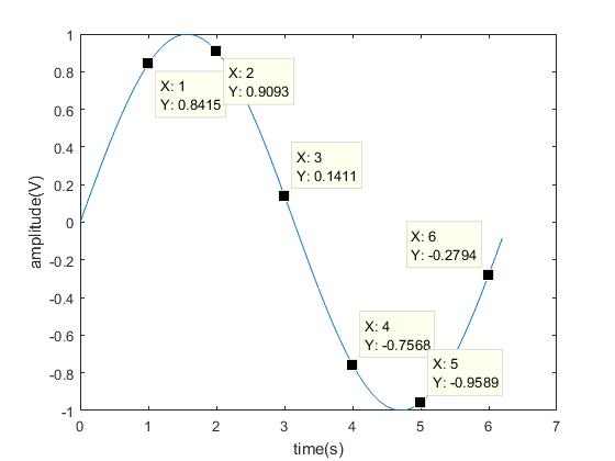
Figure 1-2 Example Wave
Consider the above example wave stored in a wav file(The data here is not realistic, it’s solely for illustration purpose). Assume the metadata in the header of the wave file tells you the sample frequency is 1Hz.
We start with an easier case, thinking from the perspective view of AM. Assume the AM device is able to magically output negative voltages, ignoring the DC offset, and assume the DAC is infinitely accurate. Because the sample frequency is 1Hz, we change the output voltage of the AM device every 1 second. Therefore, at second 1, the AM device changes the voltage to 0.8415, at second 2, the AM device changes the voltage to 0.9093, etc. Figure 1-3 shows how AM wave of this example looks like.
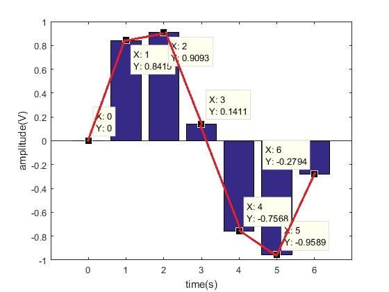
Figure 1-3 Example AM Wave
For the AM wave, the sample frequency determines how frequently we are changing the amplitude, while for the FM wave, it determines how frequently we are making frequency deviation to the base frequency of the carrier wave. The value of the amplitude, for the AM wave, is the amplitude voltage itself, while for the FM wave, it determines how much deviation to make to the base frequency of the carrier wave.
To simplify things, here we assume the carrier wave is a 100.0 MHz square wave, and the maximal deviation is ±1 MHz. Similarly, we assume the FM device is able to generate infinitely accurate square waves with respect to frequency. Because the sample frequency is 1 Hz, we are changing the base frequency of the carrier wave every 1 second. Therefore, at second 1, the value is 0.8415, we make a deviation of 0.8415 MHz, at second 2, the value is 0.9093, we make a deviation of 0.9093 MHz. Figure 1-4 shows how the frequency of the output wave as time proceeds.
| Time(s) | Base Freq(MHz) | Deviation(Mhz) | Actual Freq(MHz) |
|---|---|---|---|
| 0 | 100 | 0 | 100.0 |
| 1 | 100 | 0.8415 | 100.8415 |
| 2 | 100 | 0.9093 | 100.9093 |
| 3 | 100 | 0.1411 | 100.1411 |
| 4 | 100 | -0.7568 | 99.2423 |
| 5 | 100 | -0.9589 | 99.0411 |
| 6 | 100 | -0.2794 | 99.7206 |
Figure 1-4 Example FM Wave Table
The legal frequency band is different for different countries, so our project assumes we are located in the United States. We assume receivable band is 87.5 MHz ~ 107.9 MHz, and each station channel has a bandwidth of 0.2 MHz. This assumption applies to the receiver, the GUI, and the transmitter. Our FM transceiver is able to receive channels within United States and transmit in US Frequency band (87.5 MHz ~ 107.9 MHz). The transmitted signal of our transmitter is able to be received within a range of 20 meters using a 10 cm wire as antenna, which is enough to demonstrate the power of our transmitter, but also not illegally overwrite registered commercial FM channels.
Design and Testing top
Overall, for this project, we used an incremental design approach that developed the receiver part, GUI part, and transmitter part in isolation. After each unit has been thoroughly tested, we merged them and built our app that presents functionalities of each unit, as the demo video shows. For each step of our incremental design, we leveraged the object-oriented-programming feature of python language, and abstractly encapsulated each unit into a python package that has several classes. This approach hides implementation details of each unit, achieves better modularity, and simplifies the job of building an app.
Receiver
Our receiver is an external I2C FM Tuner (Si4703). We have several reasons to choose this device. First, using an external tuner device allows us to skip complicated details of the algorithm to decouple the wave from the high-frequency carrier wave. Second, an I2C interface saves GPIO ports of Raspberry-Pi compared to traditional DAC, yet the external device itself maintains a good accuracy with an internally integrated DAC on chip. Third, compared to other I2C devices, this Si4703 device is well documented, the datasheet and programming guide of the chip on this device is concise yet detailed. Last, this tiny evaluation board has built a reliable peripheral circuit of the chip for us and provides a breadboard friendly interface, which well matches our prototyping purpose. Next, we’ll introduce step by step how the receiver was built and tested.
Step1. Design the interface circuit and make the connection
The schematic for the FM Tuner is shown in Figure 2-1[1].
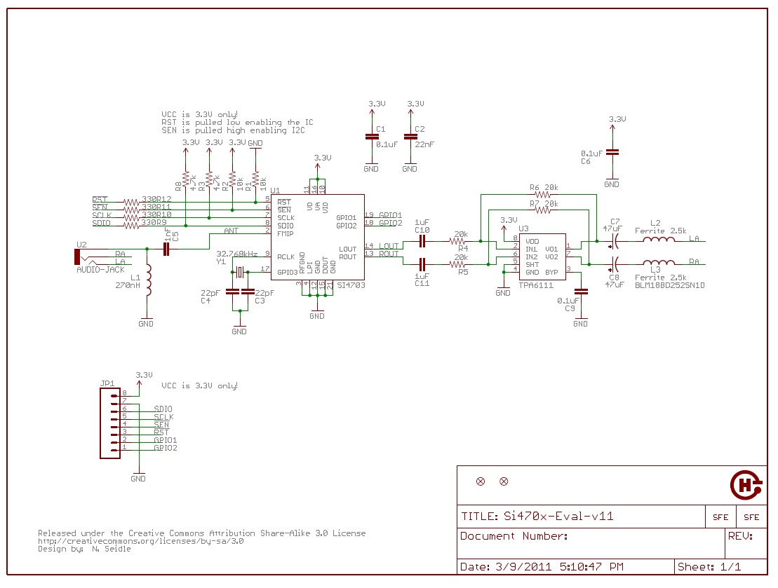
Figure 2-1 Si4703 Evaluation Breakout Schematic
Based on what is given on the circuit of the breakout, we designed the circuit shown in Figure 2-2 to connect Raspberry-Pi with this module. Most of them are straightforward connections, because pull-up resistors and the crystal oscillator are already connected. One thing that is worth mentioning here is this breakout uses the cable of the speaker or the earbud as the antenna. For GPIO 1 of the tuner, we connected it to a LED, and after the tuner is powered up, we immediately turn on the LED as an indicator of successful power-up. GPIO 2 of the tuner is used to trigger interrupts when a tuning operation has been done. Leaving nSEN pin floating allows us to select the I2C mode instead of 3-wire mode.
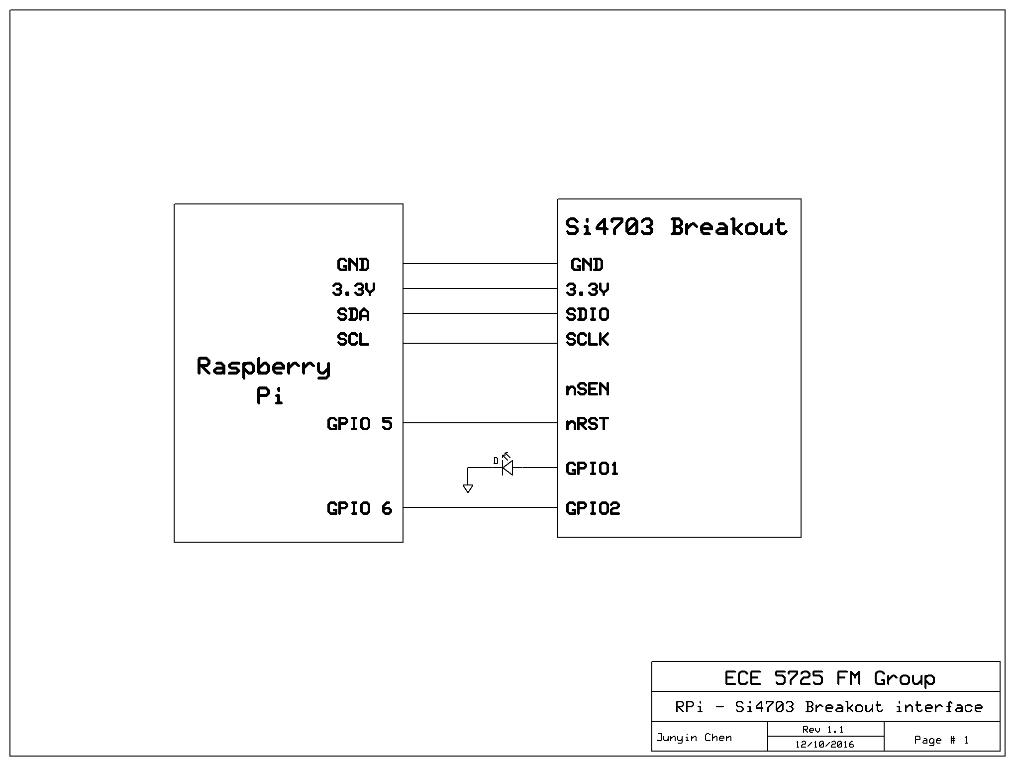
Figure 2-2 RPi and Si4703 Interface Schematic
Step2. Testing I2C Interface, build the file for constants
Before we actually use the I2C device, we firstly need to know which channel of I2C we could use. This could be done by “ls” the /dev directory. For example, for Raspberry-Pi 2 you can find i2c-1 under the /dev directory, that means you can use channel 1. Next, we need to perform a quick check to see whether or not two I2C devices are correctly interfaced, here we used i2cdetect command. By executing: i2cdetect -y 1, we check devices attached to I2C channel 1, and this command displays a matrix that tells you at which I2C address an I2C device is detected. Then, we translated register definitions, constants documented in the datasheet[2] into codes in a python file, this helps us manipulate the device at a higher level later without having to remember detailed numbers in the datasheet, as opposed to the hard-coding style.
Step3. Power Up
According to the datasheet, the hardware initialization and power up sequence is as following[2]: supply power and GND-> select modes -> reset -> enable oscillator -> enable error checking -> enable device. The breakout has already taken care of most hardware initialization for us, and step1 illustrates the connection. Our focus in on the software initialization.
The programming guide, on the other hand, gives us ideas things we need to do on the software side[3]. To reset, we need to pull down RST signal (We used GPIO 5 of RPi), delay, and pull up again for resetting. We need to set the XOSCEN bit in the tuner to enable oscillator. Again, the datasheet tells us a minimal delay of 500ms is needed here for the oscillator to reach a steady state. Next, we need to set the RDSD bit to 0x0000 to enable error checking, and set ENABLE bit to enable the entire device. After this sequence, the Si4703 tuner device would be powered up.
As a quick check of the power up sequence, we set GPIO1 of the Si4703 to output a logic high to blit the LED. Also, this operation somehow verifies I2C write is correctly done, because only when correct bits in the correct register are set will the GPIO1 output mode be properly set as we expected. Additionally, we extracted several bits that is unique to each specific device, for example, device ID, firmware version, manufacture ID, etc. We made an assertion that these unique identification bits should precisely match the value and address as specified in the datasheet. This helps verify the correctness of I2C read, and the correct match of the version of datasheet and the actual hardware.
Step4. Make configurations
Configurations after the power-up of the device include setting up blending, thresholding, regional configuration for band, space, and seeking /tuning parameters. For example, setting the band configuration to US allows the tuner to receive band 87.5 ~ 107.9 MHz only. Again, this is done by setting up registers in the tuner via I2C interface. Based on the fact that this device only has 16 registers that are visible to I2C channels, and the previous step has already verified I2C read and correct version of datasheet, we exhaustively read all registers, and check whether or not these bits are properly written into proper bits with properly values as the datasheet specifies. This step makes necessary configurations for the device, and makes stronger case to prove our I2C write is functional.
Step5. Tune
At this stage, we only need to set proper bits in proper registers to indicate the frequency of the channel we want to receive. Some conversions and sanity checks have to be done, for example, we need to saturate the frequency to the bound value when a user specifies an invalid value. Besides, the resolution of the device is not infinite, so we need to round the input value to 10 bits. If everything goes smooth, at this stage, the device is able to receive valid channels and playback the music. In addition, we bought a commercial radio receiver as a functional level model, tuned this commercial receiver and our receiver to the same frequency, and compared the received audio to see if they match. This performs a good sanity check for the validation of our implementation.
Step6. Add features for preference
The previous steps thoroughly verified the functionality of our receiver, now we can add features to allow users to change some setting with ease, for example, setting volumes. These operations are nothing new, but at this stage, we can verify these features only by looking at or listening to easily observable phenomenon at a very high level, such as the volume. One thing that is worth mentioning here is this step really requires to check invalid inputs the user might make, for example, setting the volume to 200% doesn’t make much sense, we instead saturate that to 100%. This step enhances user experience, and makes better encapsulation to prevent subtle yet potential tricky bugs that might be introduced by improper usage from the user.
At this stage, the receiver part has been implemented and thoroughly tested. However, previous steps are not as smooth as we documented. Below are issues we met in these steps.
Issue1. No random data access support, read/write address not aligned.
As specified by the datasheet[2], this device does not support random data access, and we’ll have to access the register sequentially. Also, the starting address of read and write sequential access is not aligned(0AH for read and 02H for write). That is to say, every time we make a read transaction, it always starts at the upper byte of 0AH, then lower byte of 0AH, then upper byte of 0BH, and so on. That being the case, for read, it forces us to go through several dummy read stages and cast unnecessary data. For write, it makes a worse case that we’ll have to go through several dummy write stages without corrupting the previous value.
Our solution is to use a read-modify-write approach to facilitate partial-write. However, the misalignment of read/write starting address makes this approach error prone. Therefore, every time when we want to access data, we access the entire register file, this approach is definitely expensive, but based on the fact that this I2C device only has 16 registers (each is 2 bytes), it’s affordable. Also, we added a buffer in software, so we can combine several writes to buffer (for example, several different bits need to set for the single power-up sequence), rotate the buffer to address misalignment problem, and finally flush the entire buffer (32 bytes) to the entire 16 register file. This maximally reduces expensive operation to read or write entire 32 bytes of data.
Issue2. Incompatibility with smbus library
The smbus is a common library to use for a master Raspberry-Pi and an external slave I2C device. However, this python library is not very compatible with our Si4703 device. We found this incompatibility by discovering that the write operation is always off by 1 byte, and smbus library only maximally support 32 bytes within a single read or write transaction. That is to say, initialization sequence of writes in this library would be recognized as the first valid write transaction by the Si4703 device, so the first write always writes bogus data. We resolved this by calling lowest possible library, for example, io, fcntl, and struct, to manipulate the raw I2C device file descriptor. The I2CRaw.py file shows the detail.
Issue3. Low success rate on tuning
At first, we found the tuning transaction only succeeds 5% of time, with exactly same code.We exhaustively checked all bytes of all control registers and we are very sure all of them are properly written. We discovered that it only succeeds when we kill the previous script, and restart the script really fast. To simulate this process, we added a short reset signal before we actually send the tune signal to our device, and the tuning process now succeeds 100% of time. Also, as discussed in earlier section, our write approach flushes the entire buffer, so this write after short reset does not corrupt previous states. This short reset is not specified by the datasheet, but it resolves the problem at 100% of time. We suspect there might be some detailed timing in the datasheet we failed to notice, and we understand our solution is a little bit wacky. Temporarily, we’ll keep our solution as the fix to this problem, but we welcome readers to tell us a more elegant solution.
GUI
The pygame framework gives us a powerful base to build applications with GUI, but the API of this framework is not concise which forces the user to keep track of too many details. Based on the motivation to regroup pygame resource and makes a concise GUI framework for ourself, we decided to develop our own GUI classes. The GUI part of this project mainly consists of three parts, GUIPageManager class, GUIPage class and GUIButton class. The GUIPageManager class is used to switch among different pages, detect the mouth click and control the overall workflow of the application. GUIPage class is a page template shown on the screen, which contains multiple buttons. GUIButton is the button shown on the page and we can specify the callback function that is corresponding to the button. Using these classes, we can easily add pages to applications, add buttons to pages and control these pages to build the architecture of the application. This is good for the fast application development. More implementation detail are discussed below.
GUIPageManager:
The GUIPageManager class controls the application overall workflow. The workflow mainly consists of 3 parts.
1. Page control. The GUIPageManager class can easily manage pages in the application. For example, the manager can switch shown page from one page to another, this is used when we click the receiver button, and the page shown on the screen switched from the main page to receiver page.
2. Page rendering. The GUIPageManager would render the current shown page on the screen.
3. Mouse detection. The GUIPageManager is also corresponds to mouse detection of the application. Once one click is detected, the manager would call the corresponding callback function.
The main fields and methods of this class are shown below:
| Fields | Type | Meaning |
|---|---|---|
| curPageNum | int | The index of current page shown on the screen |
| curPage | GUIPage | Current screen showing page |
| pageNumCount | int | Total number of pages |
| pages | list | List of pages |
| on | boolean | Whether the manager is alive |
Field Table of GUIPageManager Class
| Method | Meaning |
|---|---|
| add_page() | Add one page to GUIPageManger and return the added page |
| render() | Render the current page |
| _mouse_detect() | Method detection function |
| _turn_to_page(page, set_parent = true) | Turn to another page and whether set the current page as the turned page’s parent |
| control_enable() | Enable mouse detection by starting a mouse detection thread |
| control_disable() | Disable mouse detection and terminates the mouse detection thread |
Method Table of GUIPageManager Class
GUIPage:
The GUIPage class is a page template that can be shown on the screen. We can add multiple buttons on the screen by specifying the button’s properties. Every page is implicitly initialized with one exit button that can be used to exit the application.
The main fields and methods of this class are shown below:
| Fields | Type | Meaning |
|---|---|---|
| buttons | list | List of buttons on the page |
| manager | GUIPageManager | Manager that controls the page |
| num | int | Index of current page |
| parentNum | int | Index of parent page |
Field Table of GUIPage Class
| Method | Meaning |
|---|---|
| _blit() | Render the buttons on the page |
| add_button(text, pos, size, color, callback) | Add one button to the page by specifying the button’s properties |
| _get_clicked_button(x, y) | Get the button that corresponds to the x, y position |
| _exit_callback() | Callback function that will be called when exit button is clicked |
| _back_callback() | Callback function that will be called when exit button is clicked |
| _add_exit_button(pos, size, color) | Add an exit button |
| add_back_button(pos, size, color) | Add a back button |
Method Table of GUIPage Class
GUIButton:
The GUIButton button is a button template that is shown on the page. Users can specify the button’s properties such as size, text, position, color, etc. Here, we use the rectangle as the button’s shape.
The main fields and methods of this class are shown below:
| Fields | Type | Meaning |
|---|---|---|
| font | Font | Font of the text on button |
| page | GUIPage | Page the button is on |
| text | string | Text on the button |
| pos | tuple | Position of the button |
| color | Color | Color of the button (text) |
| callBack | function | Callback function when button is clicked |
| extraCallBack | function | Extra callback function when button is clicked (needed especially for back button, some additional operations need to be done) |
Field Table of GUIButton Class
| Method | Meaning |
|---|---|
| update_text(text) | Update the text on the button |
| extra_callback(callback) | Add one callback funtion that would be executed when the button is clicked |
Method Table of GUIButton Class
Usage:
It’s easy to develop an application using these three classes. Users can initialize one GUIPageManager to control page switch and mouse detection. Then users can add pages to the manager using GUIPageMagager.add_page() function. After that, users can add multiple buttons to pages by GUIPage.add_button(text, pos, size, color, callback) function. At this point, the architecture of the application is finished and user can add logics to the application.
We use the following steps as a quick example to build an application:
Step1: Create GUIPageManager
manager = GUIPageManager(debug = debug)
Step2: Add main pages with Transmitte button, receiver button with callback function
      # page0 -> page1

def p0_button0_callback():

    manager.turn_to_page(page1)


# page0 -> page2

def p0_button1_callback():

    manager.turn_to_page(page2)


page0         = manager.add_page()

p0_button0    = page0.add_button("Transmitter", (160, 80), 40, WHITE,
           call_back = p0_button0_callback)

p0_button1    = page0.add_button("Receiver", (160, 140), 40, WHITE,
           call_back = p0_button1_callback)
We can get the following page:
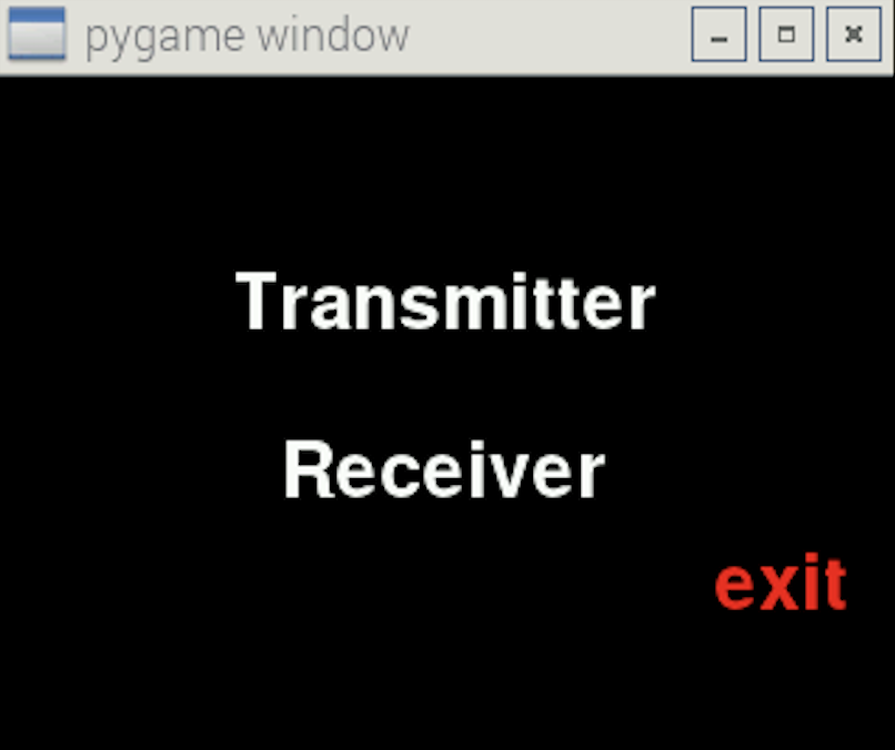
Figure 3-1
Step3: Add a new receiver page with seek button.
  page2          = manager.add_page()

p2_button0     = page2.add_button("seek", (160, 80), 40, WHITE)

p2_back_button = page2.add_back_button()
We can get the following page:
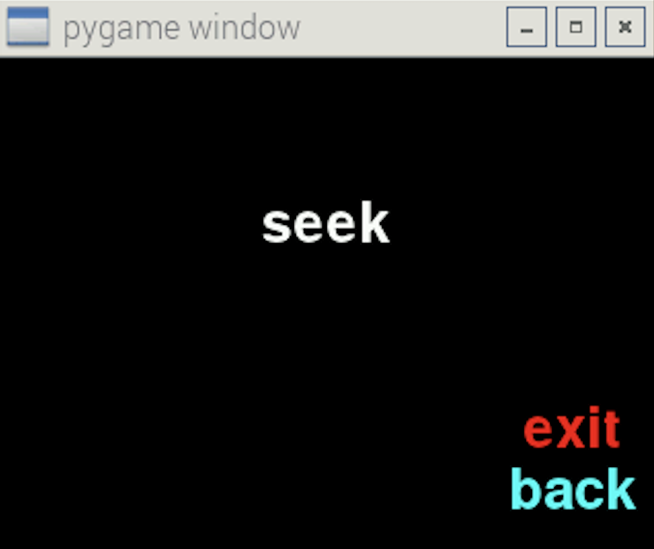
Figure 3-2
The rest we just need to do is to add logic to this application by specifying corresponding callback functions of different buttons.
We encountered some issues when developing the GUI classes, and we will discuss these issues below:
Issue 1: Multiple Inheritance
We are faced with a page multiple inheritance problem that one page can might have multiple parent pages. For example, when we want to change the receiver and transmitter frequency, we click the tune button and goes to tune page. However, when going back from tune page, there are two possibilities: receiver page and transmitter page. To solve this problem, we add “set_parent” parameter to the turn_to_page(page, set_parent = true) method with a default True value. This means we implicitly set the current page as the parent page of the turned page on page transition, and that allows the user to go back to the most recent parent. However, we allow users to explicitly skip the set parent operation, which is particularly useful for the “back” button to avoid the interlock.
Issue 2: Mouse Click Detection
Some mouse clicking may not be detected if we use a big while loop to detect mouse and then render pages. This is because that rendering takes significant CPU resource and lost response to click. One Solution is to use the interrupt mechanism. However, pygame doesn’t support this feature. Therefore, we use another strategy by spawning a thread to collect mouse clicks. In the mouth detection thread, we keep polling events, detecting the button that is clicked and executing the corresponding callback function. Also, this guarantees the concurrency of the entire system.
Issue 3: Unclean quit
When we click the exit button, the application can’t exit successfully. The reason is that the main application is terminated, but the mouth detection thread is still running. Therefore, we need to explicitly terminate the mouth detection thread in order to exit the application successfully. We use a field “on” to record whether the application is working (on), and the mouth detection thread is running with a while loop (while self.on). When the exit button is clicked, we set the self.on to False, thus the mouth detection thread is able to terminate and the whole application can exit successfully.
Issue 4: Extra callback for “back” button
We added extraCallBack field to GUIButton class which is mainly used by “back” button. This is because the callback function for back button is implicitly used for only getting back to the parent page. However, the user might also want to do some other operations. For example, when the application goes back from receiver page to main page, we also want to mute the volume. And this extraCallBack field attaches extra operations (the mute method in this specific example) to the “back” button.
In this section, we introduced three new classes, GUIPageManager, GUIPage and GUIButton, which are designated to support fast prototyping of control flow with GUI page transition. By using these three classes, users can build the application structure easily and focus on the logic and functionality of the application. However, there are still some disadvantages about our implementation, for example, these classes are pygame-based so they are heavy. Also, the button is text-only and unable to move, which makes our GUI not suitable for animation purpose.
Transmitter
We got the inspiration of our transmitter from an example project[10]. Our transmitter is a software FM transmitter that implements modulation solely relying on the hardware resource of Raspberry Pi. For the receiver, using external device makes sense since the receiver only needs to extract the modulated wave from carrier and send extracted signal to the speaker. However, for the transmitter, it is less than ideal because the external device typically does not host a file system and cannot assume the format it should transmit. Even if with an external transmitter, the Raspberry-Pi needs to decode the wave file and send samples to the external device at the first place. Considering the fact that this intermediate step of transmission from the Raspberry-Pi to the external transmitter device only adds one extra layer of complexity, and the Raspberry-Pi has the full view of the wave file, we determined that modulating and transmitting locally on the Raspberry-Pi is the ideal choice.
The introduction section gives a contrived but illustrative example to show how FM works. In the realistic scenario, the difference is now the analog waveform is instead encoded to digital wav files. To actually implement FM, there are several key questions we must answer. (1). What is the sample frequency of the wave? (2). What is the maximal value of one sample? (3). How is one sample represented? We need to answer these questions because: (1). The modulator needs to decide how frequently it needs to make deviation to the base frequency. (2). The value of one sample is proportional to the maximal deviation of base frequency. The modulator needs to scale the value of one sample to make the proper deviation. (3). Based on different formats, one sample could be 8 bit or 16 bit, one channel or two channels. Knowing how one sample is represented is essential to correctly interpret the value of one sample.
The above three questions capture the spirit of our design. Our software transmitter is composed of 4 key parts, a wave reader, a wave header, a format summarizer, and the transmitter itself. The wave reader reads a wav file, and keeps track of the pointer of the file. A wave header remembers the metadata of the file. The format summarizer centralizes several key elements of the metadata. Finally, the transmitter itself collects samples and makes the frequency modulation.
The wave header helps the wave reader to separate the metadata and actual blocks of data that represent samples. Because actual sample blocks are large, copying the entire file to memory is very expensive, so we decided to copy the metadata into a buffer (a wav header), and for the sample blocks we only keep a pointer of the file. What’s more, even if metadata are all stored in the wave header, we still built a format summarizer class to extract the format. This is not redundant, the idea of this summarizer class is similar to the cache in hardware. This summarizer class extracts several key elements in the header that are frequently visited, so it enables users to access these entries with great ease, and this presents better spatial locality for the hardware cache to exploit as well. In addition, even if python provides standard wave libraries, we still instead decided to build our own wave reader for the following reasons. First, we want to make our wave reader lightweight, but of course this is done at the cost of less compatibility with various formats. We currently only support a canonical PCM wav format. Second, we want to expose the need of transmitter, and customize the wave reader to simplify jobs of the transmitter. This would be more detailedly discussed in a few pages. Next, we’ll discuss incremental steps to build and test our transmitter.
Step1. Decode the wav file
The canonical PCM wave format contains a 44-byte header, and figure 4-1, figure 4-2 below shows how each field in the wav file looks like and what each field means, respectively[4].
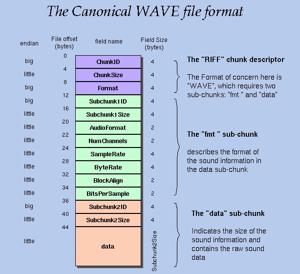
Figure 4-1 The Canonical Wav Format
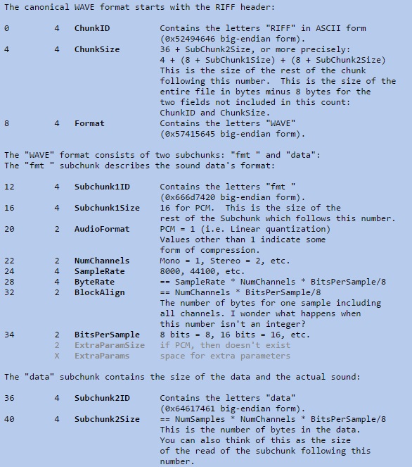
Figure 4-2 Wave Header Fields
This step answers the first question, sample rate, which could be found at byte 24 of the header. Also, this steps provides required information to answer question (2) and (3). Several key fields that worth highlighting here are: byte 22, number of channels, byte 34, bits per sample for a SINGLE channel, and byte 32, block align, which means the number of bytes for one sample including ALL channels. As a test for this step, we performed several ID checks here, for example, byte 0~3 are asserted to be characters “RIFF”. This not only guarantees the wav file we are using is strictly following canonical wav formats, but also verifies we are interpreting metadata correctly. Besides, we compared the format information listed by the operating system with our reader. This makes an even stronger case to convince us the reader we built is functional.
Step2. Determine the value of one sample
This step answers question (2) and (3). Byte 34, bits per sample indicates the maximal value of one sample. For example, 8 bits per sample means a range of 0 ~ 255, and 16 bits per sample means a range of (-32768 ~ 32767). This answer question (2). Byte 32, block align, indicates the number of bytes we need to take for one large sample, and byte 22 tells us the number of channels that helps us extract one sample for each specific channel from the one large sample. Since our FM Tuner only transmits through a single pin, multiple channels do not make much sense, we take the average value of all channels for one sample. This answers question (3). Figure 4-3 illustrates the detailed data packing for 8/16 bit mono/stereo PCM[5].
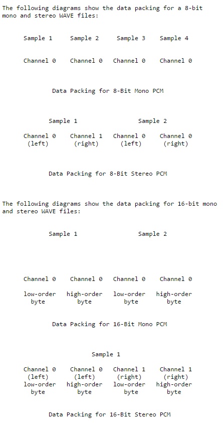
Figure 4-3 PCM Data Packing
Here comes our motivation to build the wave reader by our own. Thinking from the perspective view of the transmitter, for one sample, since the value is proportional to the maximal deviation of base frequency, the transmitter is not interested in detailed information of data packing, index of the data channel, etc. What it really cares about is the proportion of the given sample, so it can determine the amount of deviation without much conversion overhead.
For verification, we kept collecting samples one by one and record the converted proportion in a text file. We leveraged the built-in wav reader of MATLAB, and made two plots for original wav file and converted proportion data respectively, and compared the restored waveform. A match between two waveforms proves the validation of this step2. Figure 4-4 and Figure 4-5 are two examples of our comparison.
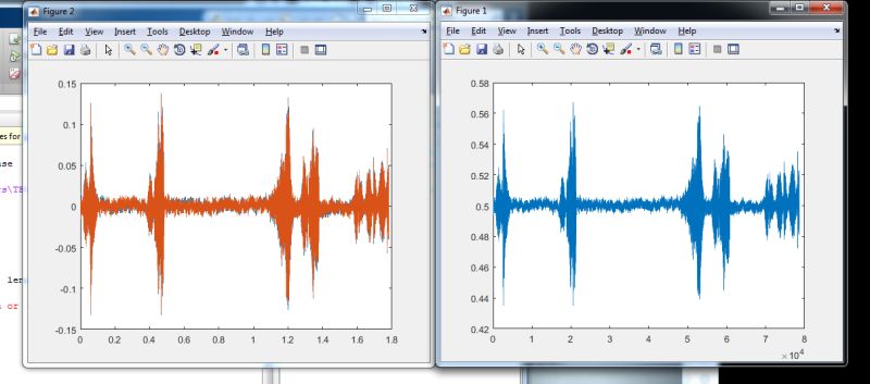
Figure 4-4 Comparison for bird.wav
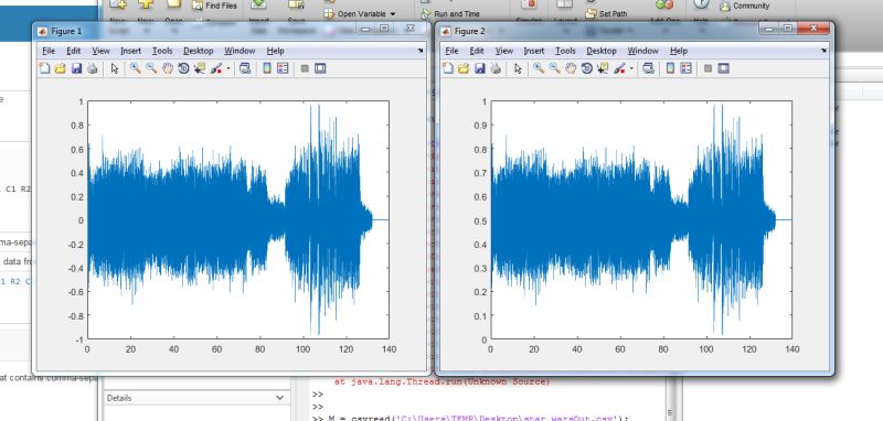
Figure 4-5 Comparison for star_wars.wav
Step3. Modulate and Transmit
Since previous two steps have answered three key questions, the transmitter only needs to finish its job at a high level. The commercial FM band for US is 87.5 ~ 107.9 MHz, and each channel might take 0.2 MHz of bandwidth. To simplify the computation, our transmitter picks a 100 MHz square wave as the carrier wave, and the maximal deviation is 0.2 MHz. When we are collecting samples, the wave reader adds a DC offset so the scaled value for one sample is a floating point from 0 ~ 1 instead of -1 ~ 1 for signed integers. We will justify this decision in the later issues part. After knowing the proportion for one sample from 0 ~ 1, the transmitter makes the frequency deviation to the carrier wave, and repeats this process until the end of the file. Ideally, at this point, a commercial receiver should be able to receive our transmitted audio, and we used a commercial analog FM receiver to verify the transmitted signal is at the correct base frequency. Since previous two steps have been fully verified, being unable to receive the transmitted signal is more than likely caused by a timing error.
After all the efforts of previous three steps, now the usage of transmitter becomes relatively simple. To build a minimal app, the usage is as simple as instantiate, init, transmit. Here is one example file that illustrates the usage of our transmitter.
Issue: High Frequency and Accurate Timing
This issue is also the most challenging part of the entire project. For one thing, we need to generate a wave with an accurate high frequency at the first place. For another, the operating system constantly interrupts the transmission task and makes actual sample rate less than ideal.
Our base frequency is 100.0 MHz, which requires a resolution of 10 ns. However, the CPU scheduling latency is at microsecond level. Using python time library or RPi.GPIO software PWM could easily attach a microsecond-level error over a nano second accuracy, that approach is guaranteed to fail. The trick we played here is to use a memory map that allows us to access Raspberry-Pi peripheral hardware resource directly, as if we are indexing into arrays. On top of that, we mapped the GPIO4 port directly to one hardware clock resource PLLD, which is running at 500 MHz. One nice feature of this resource is that the divisor of the PLL is programmable, so we used the integer part to set up the base frequency, and we used the fractional part to make the deviation. To be specific, hardware registers we accesed include the following 3: GPIO Function Select Register as documented at page 91 and 102, Clock Manager General Purpose Clocks Control Register at page 107, and system timer register at page 172 of the BCM2835 datasheet[6]. Several subtle but nasty things to mention here, (1), Raspberry-Pi 2 switched the processor (To be more accurate, SoC) from BCM2835 to BCM2836. The IO base address in physical memory map has been switched from 0x20000000 to 0x3F000000 without being documented anywhere[7]. Second, the BCM2835 datasheet only tells us we can use PLLD and System Timer without telling us the frequency. We searched on the Internet and found the information in the BCM2835 datasheet errata[8] and system timer[9] that PLLD is running at 500 MHz and System Timer is running at 100 MHz.
At step 3 of transmission, we mentioned our decision to scale the proportion to 0~1 instead of -1~1. This is due to the fact that we are using the divisor of the PLL to change the frequency and make the modulation. Assume our base frequency is 100 MHz, the integer part of the divisor is 5, and -1~1 is a natural way to connect 99.9 MHz ~ 100.1 MHz, since the bandwidth for each channel is 0.2MHz. To tune from 99.9 ~ 100.1, the divisor needs to change between 4.995 ~ 5.005. For the integer part, it needs to change back and forth between 4 and 5, and the fractional part is even worse, it has to change in a significant way. Also, to capture this accurate value of divisor, we’ll need to do several floating-point operations. The floating arithmetic is expensive, and since we had already done floating point conversion once in the wave reader, we really wanted to avoid floating arithmetic as much as possible. Therefore, we decide to keep the integer part as 5, and only change several low bits in the fractional part. We know (500 / 99.9) - (500 / 100) = 0.005, which is close to 2 to the -8. Since the fractional part has 12 bits, we only need to modify lowest 4 bits, that linearly matches proportion 0 ~ 1 to 4-bit value 0 ~ 15. This linear approximation significantly reduces floating arithmetic operations, paying at the cost that the resolution is degenerated to 4-bit, meaning the audio could only be represented by 16 different values.
Another part of the issue, operating system interruption, is resolved by the following way. (1). Access the hardware system timer directly to skip the system call and accelerate the read of current time. (2). Every time before collecting one sample, we read current time, compared with the start time, and determine the time loss due to a variety of reasons(Undefined CPU scheduling, overhead in wave reader floating point conversion, etc). (3). After knowing the time loss, the transmitter is able to realize the number of samples that should have been transmitted during the time loss duration, and the transmitter skips these samples. This essentially maintains the shape of waveform, again, at the cost of degeneration of sound quality.
Therefore, our transmitter always reads the wave file and makes the conversion and modulation on the flight. This approach is responsive, which is able to begin transaction immediately after request, at the cost of worse accuracy. Another totally opposite way of implementation could be pre-computing everything, performs whole bunch of expensive but more accurate floating-point operation before transmission. That approach maximally reduces the runtime workload, but consumes much more space to finish the job, and suffers from a worse latency. The choice of the solution really depends on the application requirement, and an ideal solution is expected to be a hybrid style of two solutions that finds the optimal balancing point between the two.
App
The application is based on the previous three parts and combines these three parts to a functional complete program.
The App UI is based on the GUI parts, we instantiated a GUIPageManager to manage the page transition and mouth detection. Overall, 4 pages are added to the manager, main page, receiver detail page, frequency modification page and transmitter page. Each page consists of different buttons that responsible for different functionalities.
The receiver page is responsible for the receiver parts and mainly interact with the receiver part above. When seek up and seek down are clicked, the radio.user_seek() function will be called to seek a new channel. When volume up and volume down buttons are clicked, the radio.set_volume(volume) function is called to change the volume, we use a global variable “vol” to record the current volume and manipulate this variable when these two buttons are clicked.
Tune page is relative simple and mainly for the string manipulation. The this page lets user specify a frequency and once go is clicked, radio.tune(fre) is called and the receiver receives the channel of specified frequency.
Transmitter page is responsible for the transmitter parts. When the application is initialized, the wav files in wav folder would be scanned and added to the playlist. Then when pause/resume button is clicked, the transmitter start transmitting the first wav file in the list and pause transmitting if the transmitter is working. Next and previous button lets user choose a file to transmit.
Incorporating the transmitter part above to application directly would cause bad effect to the transmitter that users can hardly hear the radio channel clearly. This is because the application is too heavy and transmitter is interrupted too much. To solve this problem, we use the transmitter on a separate core and use fifo to communicate between application and the transmitter. Once one button in the transmitter page is clicked, the application write the corresponding instruction to “main2Trans_fifo” fifo. then the transmitter read the instruction from “main2Trans_fifo” fifo and call corresponding functions according to the instruction. Also, we used “Trans2main_fifo” fifo to pass information from transmitter to main application. The information we pass from transmitter to application is the file name. Therefore, when the user click the pause/resume button, the application write ”resume” to “main2Trans_fifo” . The transmitter read this instruction and start transmission and write transmitted wav file name (such as “star_war.wav”) to “Trans2main_fifo” fifo. Then the application can read this and update the file name shown on the screen.
The application is a complete version of the above three parts. In this part, the main logic is implemented by calling the corresponding functions in receiver, GUI and transmitter. Since these three parts are well defined and tested, application is relative easy and straightforward to implement.
Results top
As outlined in the objective part, this project aims to construct a digital FM transceiver that is able to receive radio stations and transmit audios within a single Raspberry-Pi device. Also, to enhance the user experience, we developed a touch screen GUI that simplifies the usage of our device. We accomplished the objective for all three parts.
For the receiver, it is able to receive 5 - 7 channels. Based on our experiment, receivable channels at Cornell include [ FM 88.1 88.9 91.7 93.5 97.3 103.7 107.1 MHz]. The tuning succeeds almost 100% of time if the channel is valid. Also, because unfortunately the hardware seeking is not working, we developed a software seeking interface on top of the tuning. The software seeking is thresholding the signal strength of a channel to determine its validation. Our seeking makes an increment of 0.2 MHz every half second, and the seeking speed is primarily constrained by the speed of tuning. Recall in earlier sections we mentioned we need to add a short reset before tuning, and this reset also applies to the oscillator, which means we need extra half second to wait until it reaches a steady state. Also, the signal-strength-thresholding-based seeking scheme sometimes founds fails to recognize invalid channels when the noise signal is strong. A more robust way will be using both the signal/noise ratio and signal strength, but the hardware we are using does not support that, and this failure happens to all radio receivers.
For the GUI, we successfully built three classes which enable us to perform fast prototyping of the GUI application. Figure 5-1 is an example of main page that enables us to select modes. Figure 5-2 is an example of receiver page that supports tuning, seeking up/down, pause/resume, and displays the current frequency. Figure 5-3 and Figure 5-4 are examples of the input page that waits the user to specify a target frequency value for tuning. Figure 5-5 is the result after input. Figure 5-6 illustrates how transmitter page looks like at initial state, and figure 5-7, 5-8 are examples of transmitter pages with different files transmitting on the way.
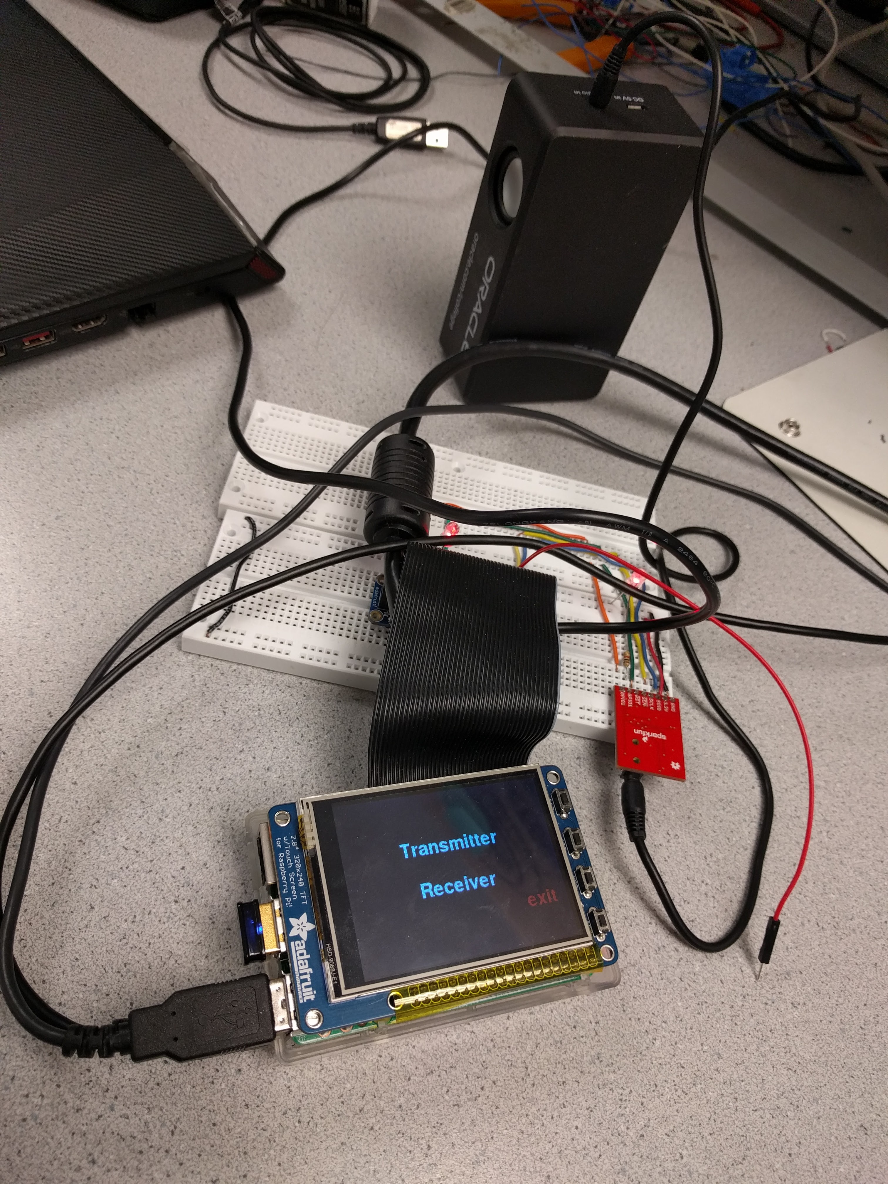
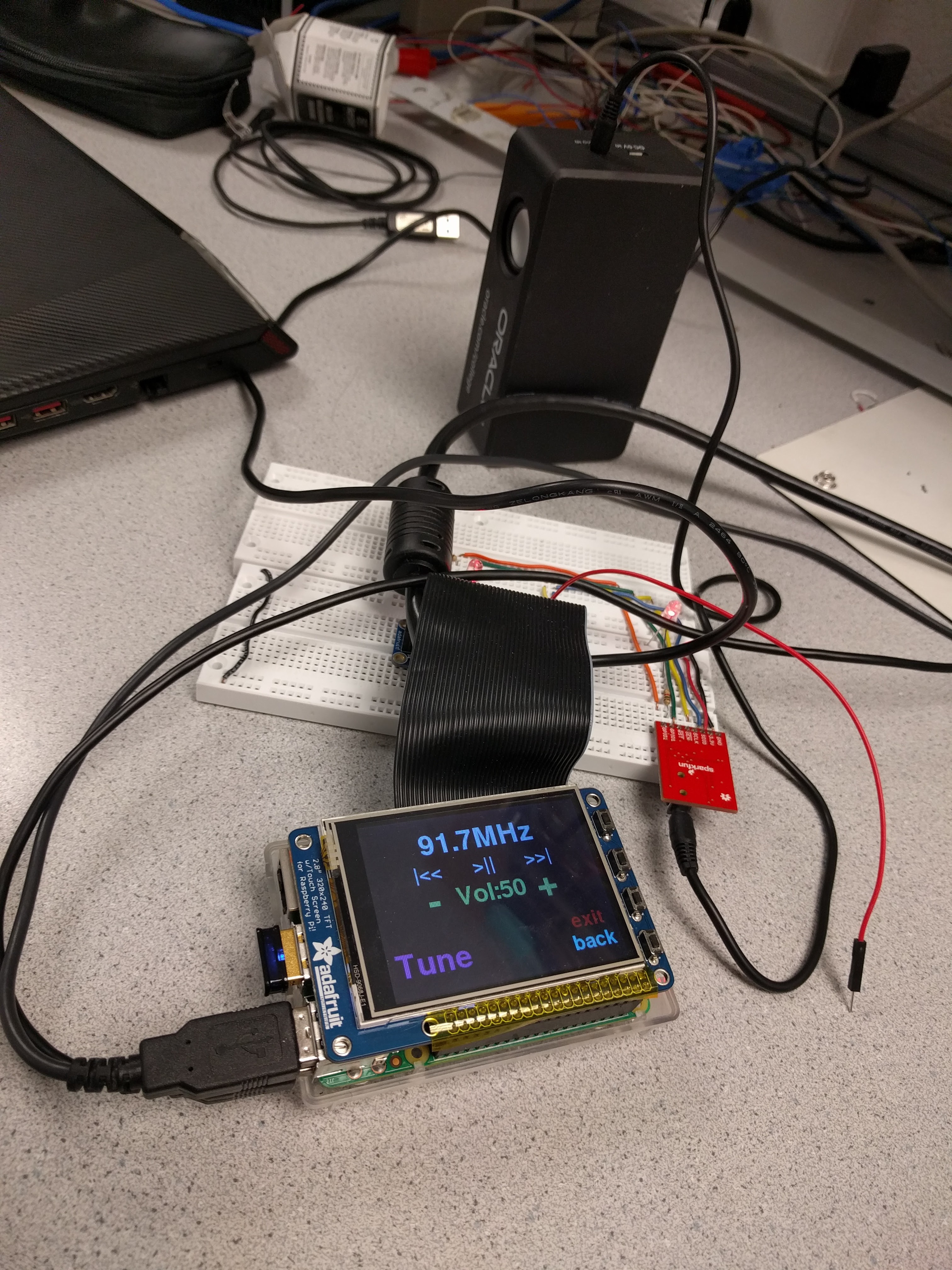
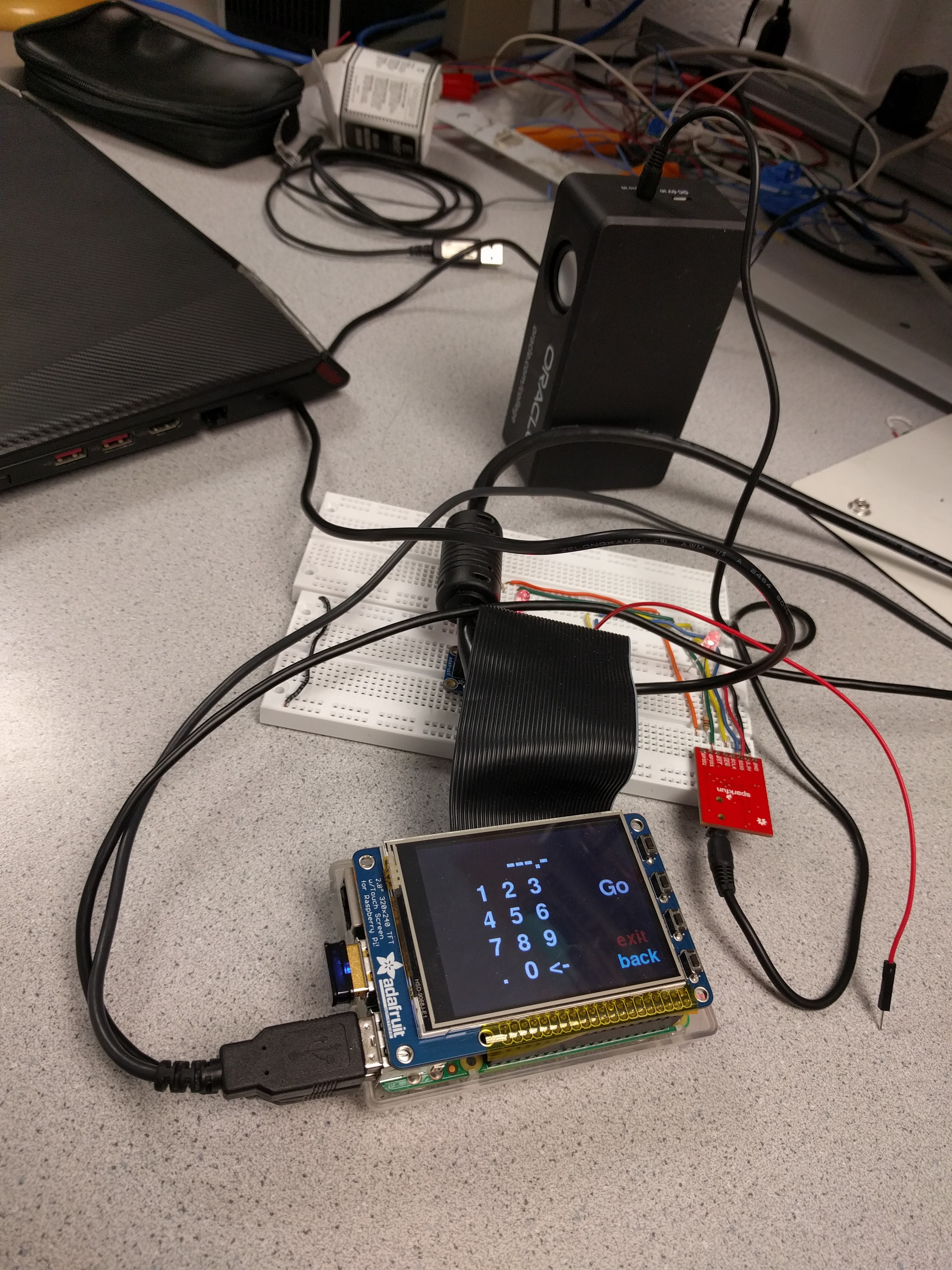
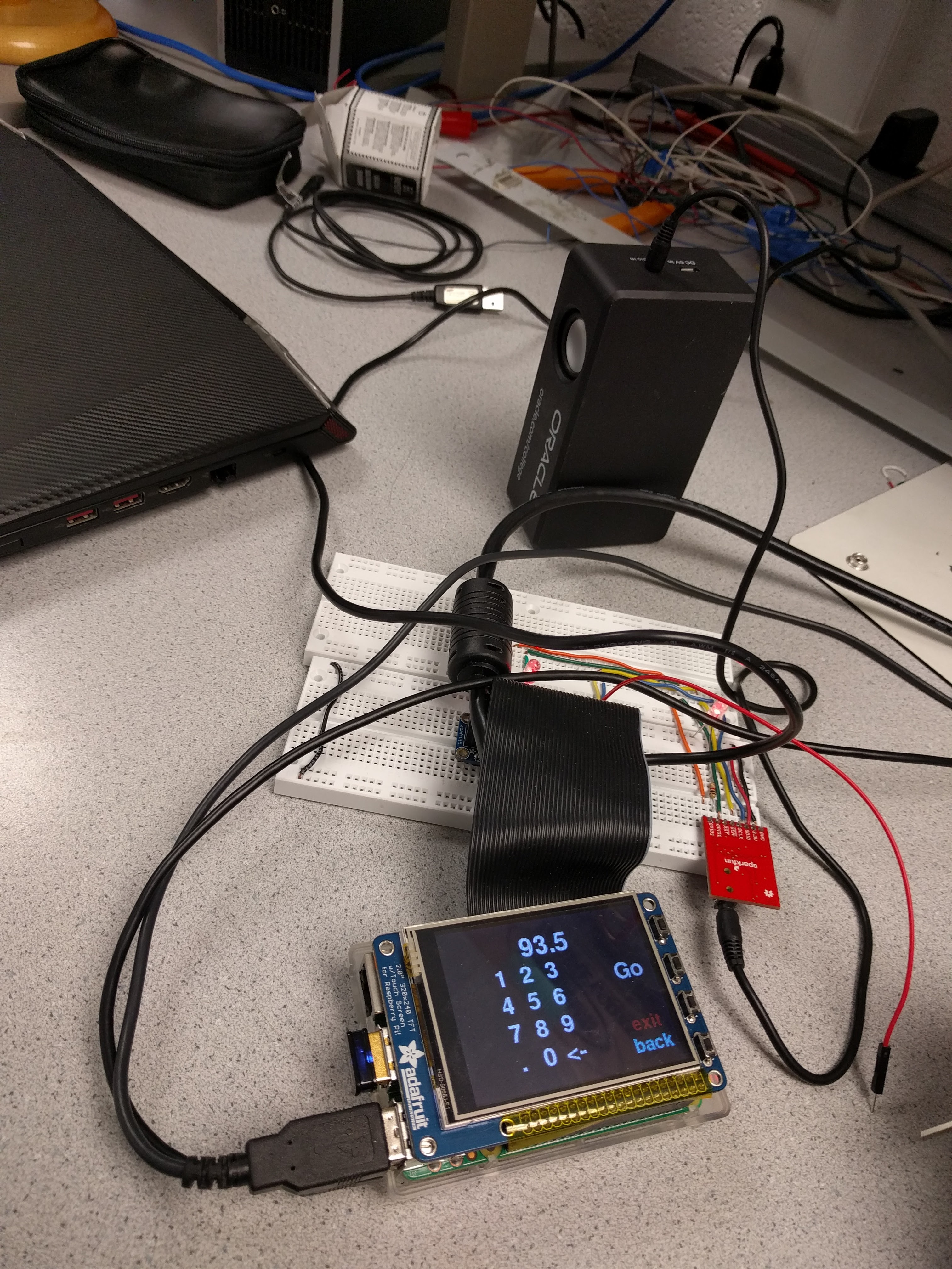
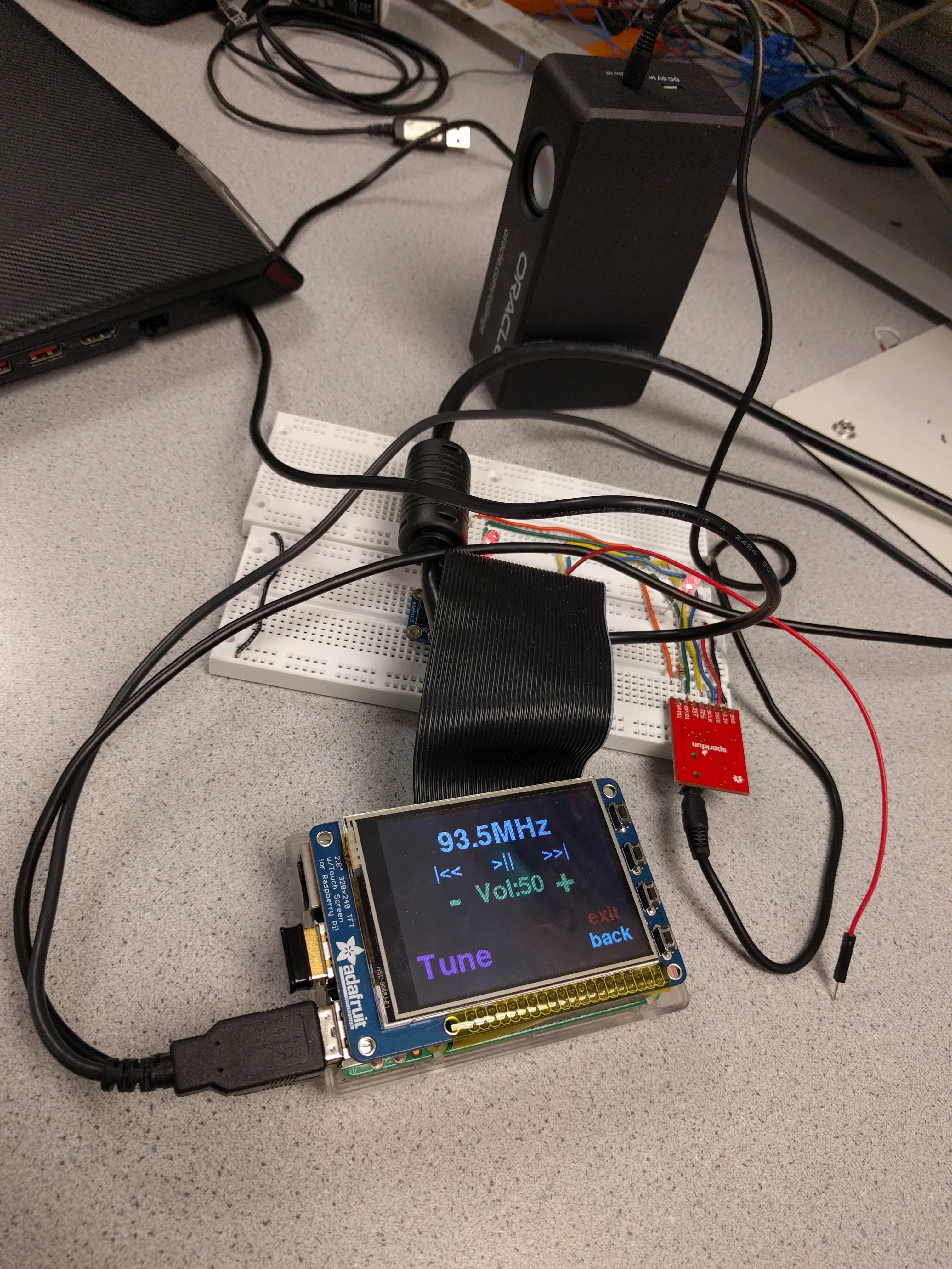
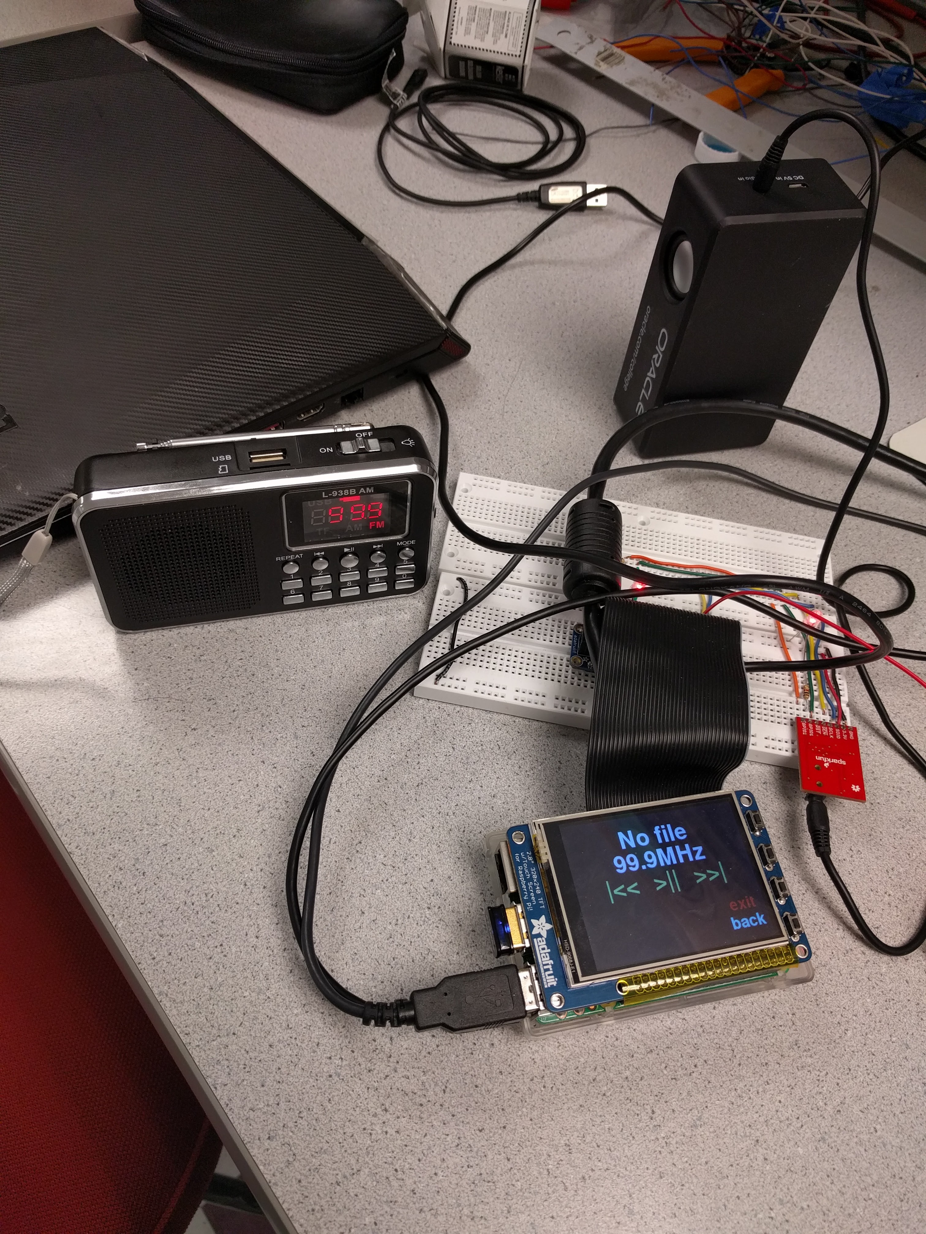
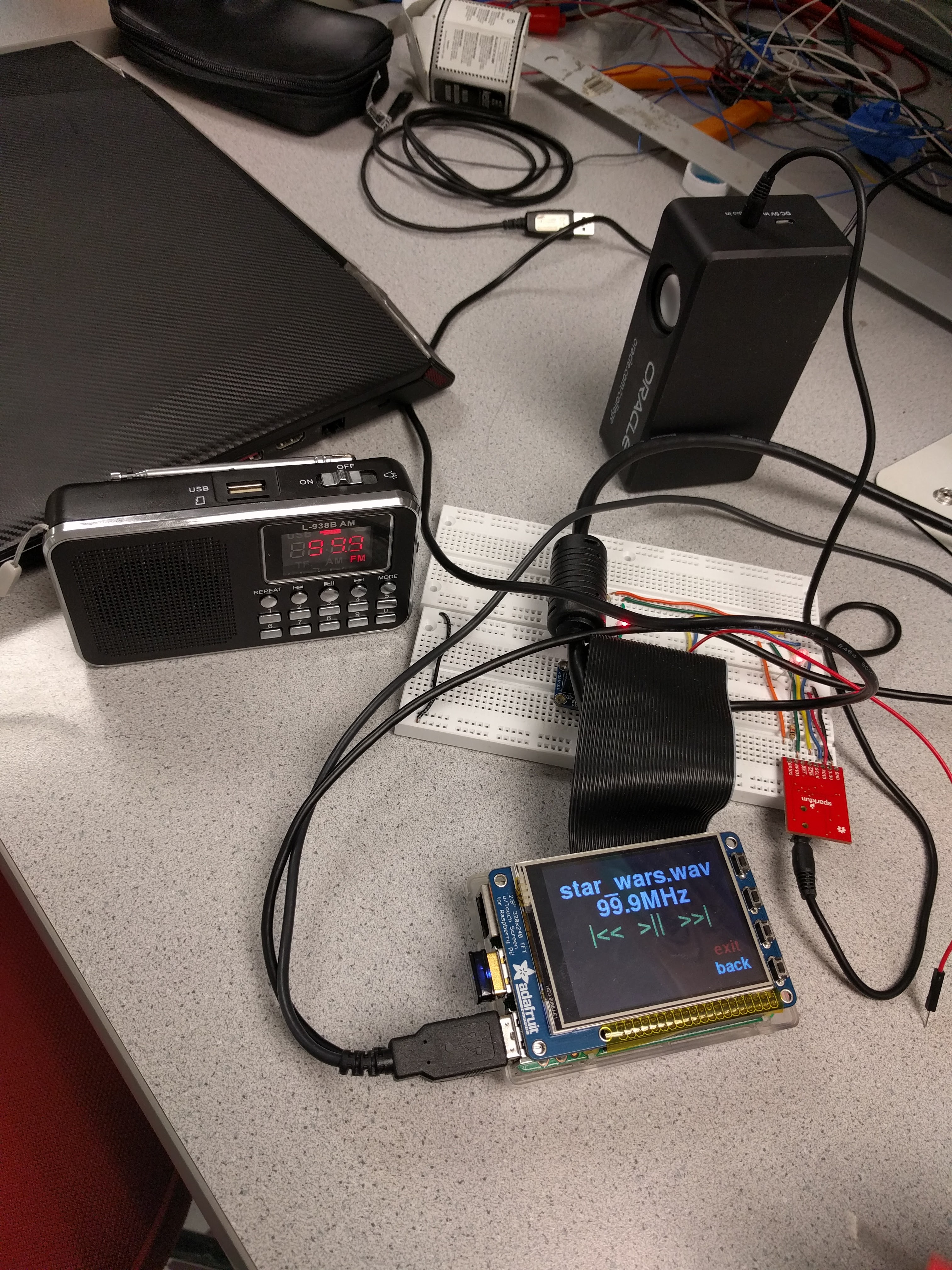
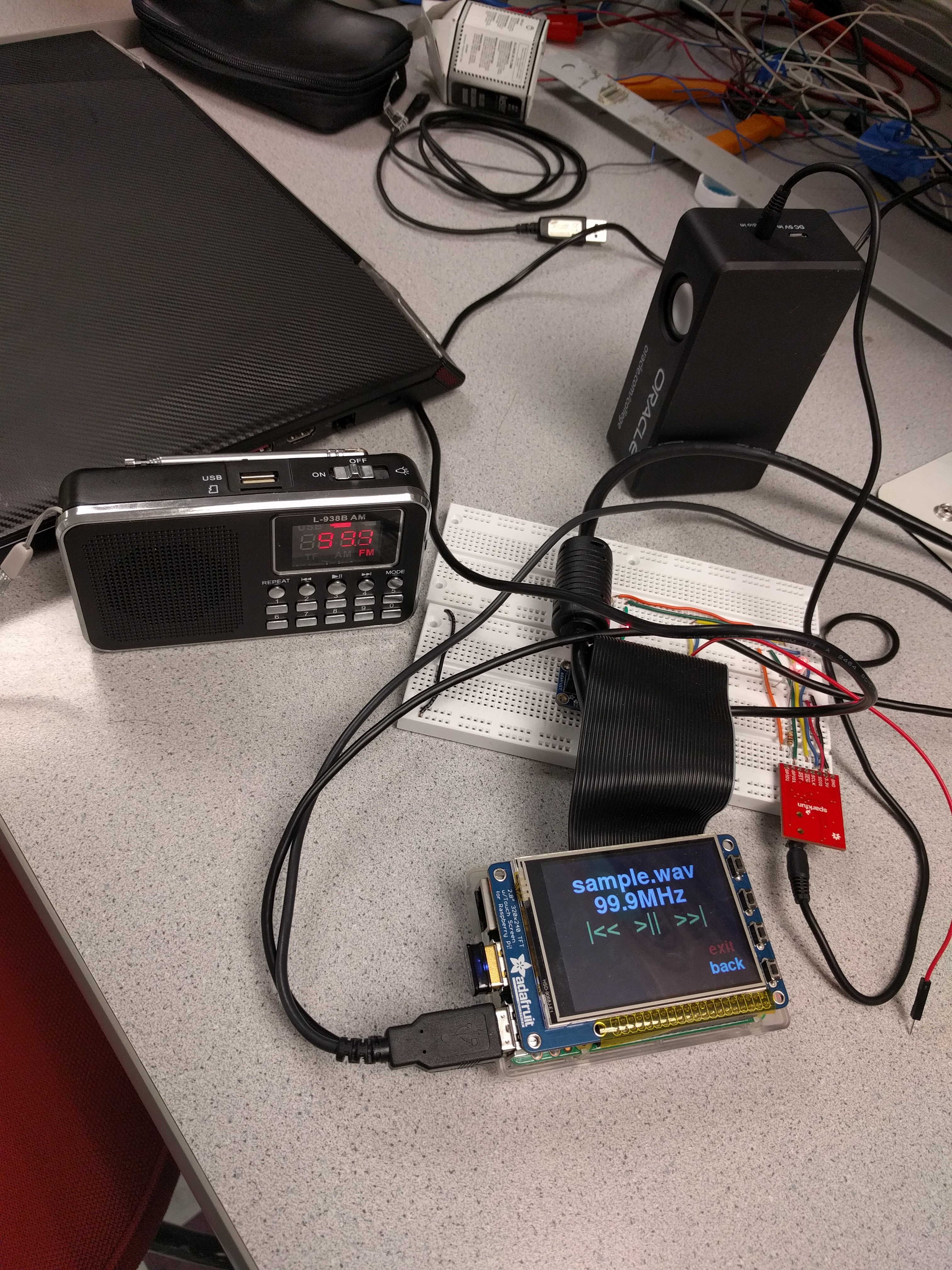
Figure 5
The transmitter is able to transmit with some noise. The noise comes from skipping samples, and using low 4 bits of fractional part of the divisor to linearly approximate the deviation. Both of them reduces the accuracy of modulation and produces noise. We limited the power of the transmitter by using a 10 cm wire as the antenna. This results in that the transmitted signal of our transmitter is able to be received within a range of 20 meters or so, enough for demo purpose, not too powerful to illegally overwrite registered commercial FM channels.
Conclusions top
Our FM transceiver project meets objectives as the project was proposed. Also, this project leverages the support from embedded operating system that distinguishes this project with traditional bare-metal microcontroller projects in a significant way. For example, the filesystem of linux allows us to add and delete audio files with great ease as long as it does not exceed the storage of SD card. Also, as opposed to hard-coded style, we leveraged python “glob” library to list audio files without having to remember the specific name of the wav files. If a bare-metal micro-controller were to be used for this project, we would have had to build SPI SD card reader, and lists of wav files, including its directory, has to be carefully hard-coded to precisely match the file path in the SD Card. What’s worse, even a minor change of SD card, such as removing files, changing the name of one wav file could easily cause the program to break. This demonstrates the advantage of embedded operating system over vulnerable bare-metal micro-controllers. Additionally, without operating system and CPU scheduling, we would not be able to spawn child threads to execute blocking tasks to maintain the concurrency of the entire system, and coordinating two different processes becomes extremely hard if we don’t have FIFO object to support inter-process communication. All these facts show the power of operating system to develop embedded projects, which is also what this embedded operating system class is all about.
Futurework top
1. The short reset solution of tuning in receiver is not ideal. There should be a more elegant solution.
2. For the transmitter, doing all computation for collecting samples and modulating on the flight is not optimal. A best approach is to find a balance between the portion of pre-computing and computing on the flight, thus to find an optimal point for response time, accuracy, and storage space.
3. Also, for the transmitter, skipping the samples is not an ideal solution. When the CPU was scheduled to do other tasks, the base frequency is kept unchanged, which might result in strong discontinuity of the wave. A possible solution might be the CPU computes the converted data to sends them to a buffer, and a DMA channel consumes the buffer and sends data to the control register or PLL divisor directly. Another possible solution might be predicting the trend of the wav, and when CPU is scheduled to do other tasks, DMA takes the control and sends predicted value to the control register or PLL divisor.
4. The GUI is pygame based, which makes the GUI heavy. If there is time, we might want to find a way to attach interrupts to collect mouse clicks instead of doing expensive polling. Besides, our GUI does not support any movement of buttons, we might be able to customize that to better support animation requirements.
Appendices top
A. Code Listing
B. Distribution of work:
| Junyin Chen | Zhenchuan Pang | Xiaokun Yu |
|---|---|---|
| System High Level Design | Assisted with GUI implementation | Assisted with part searching |
| Implemented Receiver classes | Assisted with transmitter implementation | Assisted with example code searching |
| Defined GUI classes and built the framework | Responsible for building top-level application | Assisted with verification of wave readers |
| Led in implementation of transmitter classes | Proofread constants for receiver classes | Assisted with debugging process of the transmitter |
| Came up with inter-process communication solution | Assisted with FIFO communication on application side |
Contribution Table
C. List of parts:
| Part | Vendor | Cost/Unit | Quantity | Total Cost |
|---|---|---|---|---|
| Si4703 FM Tuner Breakout | Sparkfun | $18 | 1 | $18 |
| Total: | $18 |
Part List
References top
Acknowledgements top
We acknowledge the example [10] transmitter project developed by Marcin Kondej, which gives us inspiration of building the FM transmitter. We are grateful of Prof. Skovira for his care and great support throughout the entire semester, when our project gets stuck, his advice and encouragement are particularly helpful. We acknowledge three TAs of this class, Jingyao, Brandon, Jay, for their detailed feedback on previous labs. Finally, we sincerely appreciate Prof. Land for his incredible knowledge that helps us understand background knowledges quickly, and his old but powerful analog devices are extremely helpful for testing purpose.