BioNB 442: Lab 8
Voltage Clamp
Introduction.
You will build a slightly improved active model cell, record from it, then voltage clamp the model in order to measure conductance changes.
Procedure:
Assignment
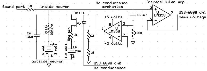
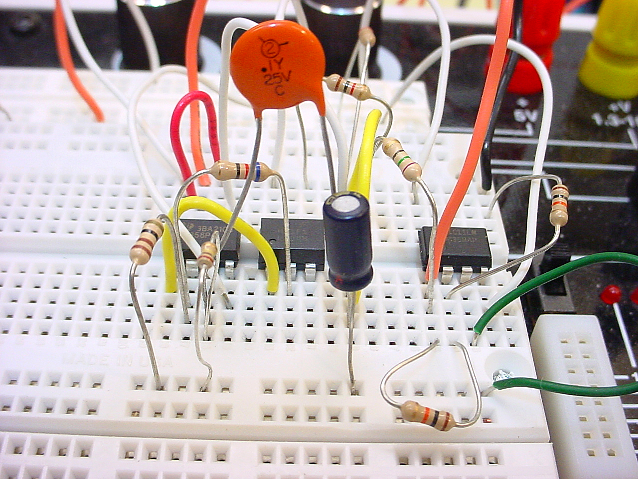
- Refering to Circuit 1 above, build the circuit, then use the physiological stimulator program described on the Matlab soft instruments page to produce pulses on the sound card output (winsound 0). The middle ring of the stereo phone jack (Channel 2, see lab 1) carries the pulses. Apply those to the model cell as shown above. Set the stimulus length to 10 mSec. You should be able to stimulate action potentials in the model and record them using gPRIME connected to the USB-6008. What is the membrane time constant of the model cell (computed and measured)? Why is the rise time of the action potential faster than the computed time constant? What is the resting potential and action potential overshoot. Explain these values based on the circuit.
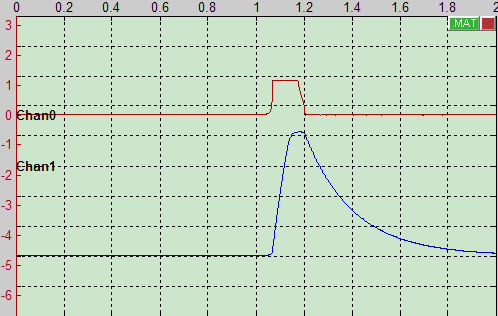
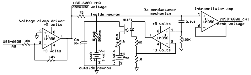
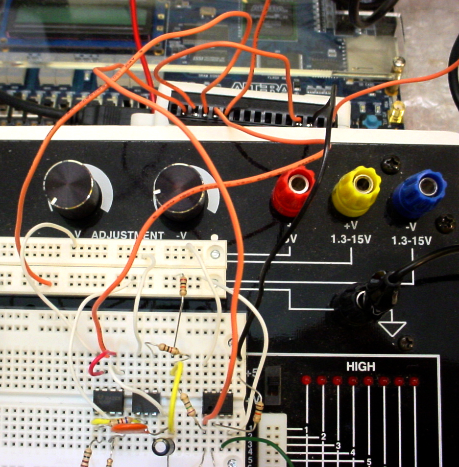
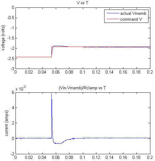
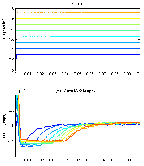
- Refering to Circuit 2 above, add the clamp driver to Circuit 1. Download lab8niVclamp.m and show that you can clamp your model cell using this code to generate the command pulses and to record two voltages as shown above. Modify the program to produce a series of voltage steps ranging from 2.5 to zero volts (-2.5 to 0 after inversion). The steps should start at 2.5 volts for 2 seconds, jump to the first step voltage for 100 mSec, then back to 2.5 volts for 2 seconds, then jump to the second step voltage for 100 mSec, and so on. The voltage and current traces should be stacked on the same plots for comparison, something like the image below. The traces here were lowpass filtered, and the linewidth was set to 2. What can you say about the voltage dependency and dynamics of the transient current? How about the steady-state current?
Your written lab report should include:
- A printout of all data screens you use for measurements.
- A commented listing for the voltage clamp programs.
July 2007 Copyright Cornell university