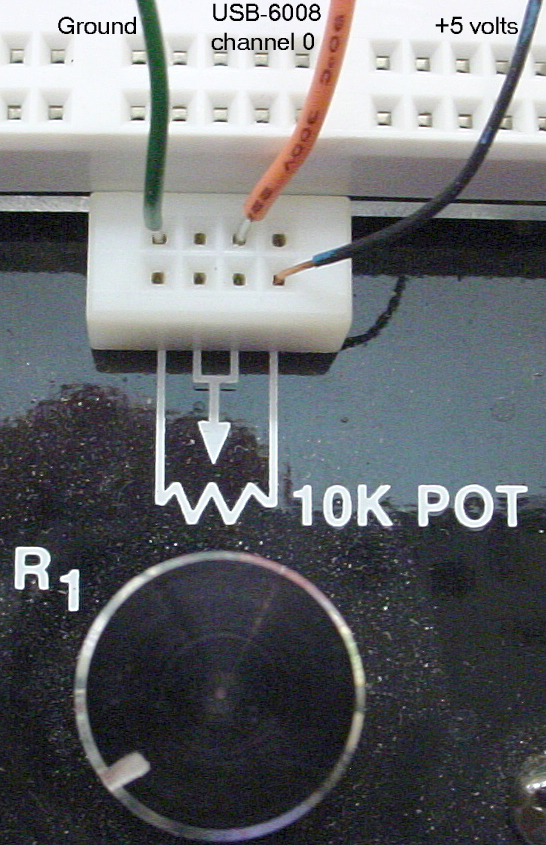
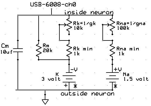
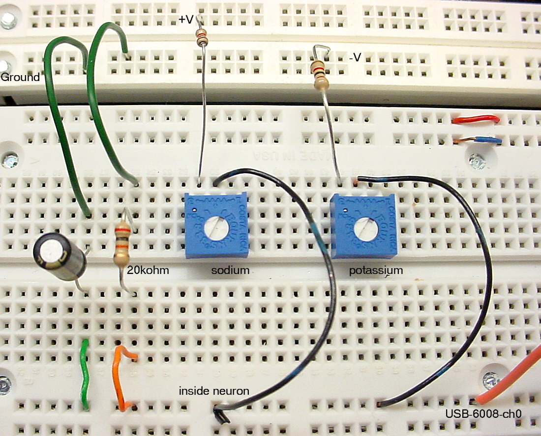
Build the circuit shown below. The circuit is based on information given in the reference at the bottom of the page. It is a simple simulation of a small piece of neuronal membrane with three channel types modeled as resistances. A lower resistance (higher conductance) implies more open ionic channels. The three conductances are a fixed leak, variable sodium and variable potassium conductance. The two connections to the batteries marked with asterisks are internally connected in the protoboard. Set +V to 1.5 volts and -V to -3.0 volts. These voltages are about a factor of 30 bigger than in actual neurons. Your manipulation of the conductances will be about 1000 times slower than a real action potential.
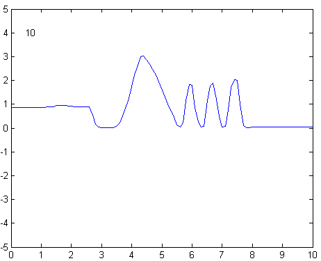
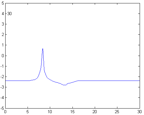
An example action potential simulation is shown below. The soduim conductance was increased quickly then decreased, while the potassium conductance was increased slowly, then decreased slowly. When wired as shown above, minimum conductance corresponds to the potentiometers completely counter-clockwise. Notice that the potential overshoots zero, as in a typical action potential and that there is a prolonged hyperpolarized undershoot caused by a long, active potassium current. (Waveform below produced by Dustin Rubinstein.)
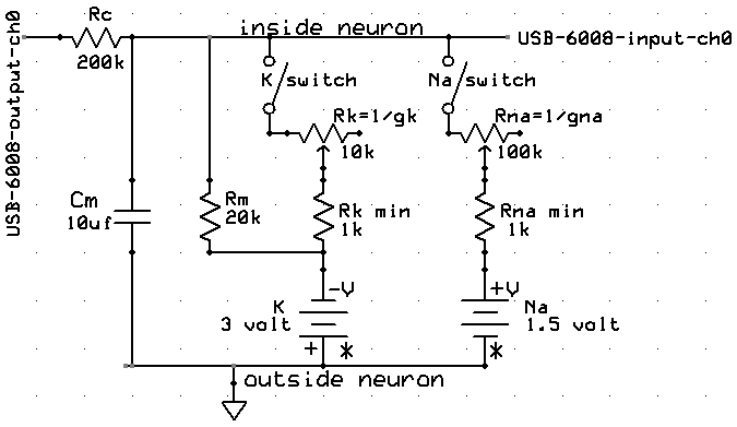
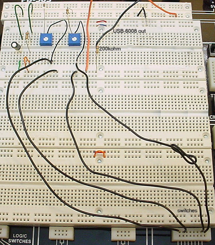
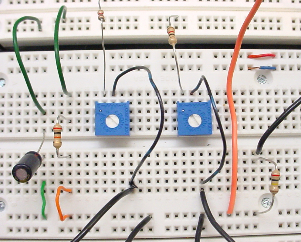
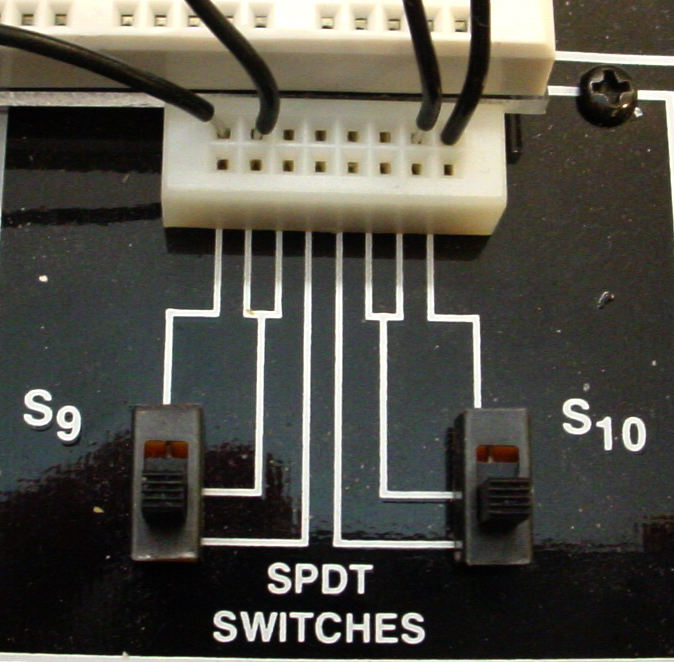
This circuit is a slight modification to Circuit 1. You need to disconnect 2 wires to insert switches and add an output from the USB-6008 to use as a stimulus. With this circuit, you will act as the voltage detector to trigger an action potential when you notice a depolarization. The schematic and three views of the protoboard are shown below.
You can set up the USB-6008 to produce a voltage using a scheme like that shown below.
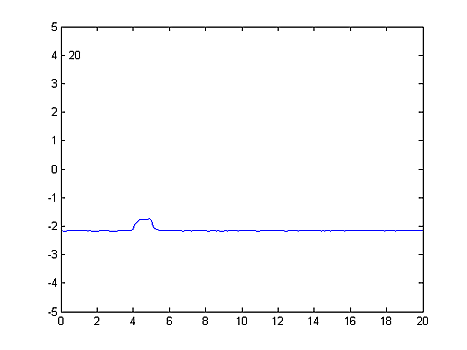
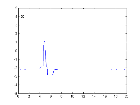
ao = analogoutput(adaptor, id);
chOut = addchannel(ao, [0]);
putsample(ao,0.0) %output zero volts
Two traces are shown below. The first shows just the stimulus. The second shows my attempt at behaving like a voltage-triggered conductance generator by turning on the sodium conductance switch, followed by the potassium conductance switch. Both of the potentiometers were set to maximum conductance.